EE445M RTOS
Taken at the University of Texas Spring 2015
Udma_api

Data Structures

struct  tDMAControlTable
 

Macros

#define uDMATaskStructEntry(ui32TransferCount, ui32ItemSize, ui32SrcIncrement, pvSrcAddr, ui32DstIncrement, pvDstAddr, ui32ArbSize, ui32Mode)
 

Functions

void uDMAEnable (void)
 
void uDMADisable (void)
 
uint32_t uDMAErrorStatusGet (void)
 
void uDMAErrorStatusClear (void)
 
void uDMAChannelEnable (uint32_t ui32ChannelNum)
 
void uDMAChannelDisable (uint32_t ui32ChannelNum)
 
bool uDMAChannelIsEnabled (uint32_t ui32ChannelNum)
 
void uDMAControlBaseSet (void *psControlTable)
 
void * uDMAControlBaseGet (void)
 
void * uDMAControlAlternateBaseGet (void)
 
void uDMAChannelRequest (uint32_t ui32ChannelNum)
 
void uDMAChannelAttributeEnable (uint32_t ui32ChannelNum, uint32_t ui32Attr)
 
void uDMAChannelAttributeDisable (uint32_t ui32ChannelNum, uint32_t ui32Attr)
 
uint32_t uDMAChannelAttributeGet (uint32_t ui32ChannelNum)
 
void uDMAChannelControlSet (uint32_t ui32ChannelStructIndex, uint32_t ui32Control)
 
void uDMAChannelTransferSet (uint32_t ui32ChannelStructIndex, uint32_t ui32Mode, void *pvSrcAddr, void *pvDstAddr, uint32_t ui32TransferSize)
 
void uDMAChannelScatterGatherSet (uint32_t ui32ChannelNum, uint32_t ui32TaskCount, void *pvTaskList, uint32_t ui32IsPeriphSG)
 
uint32_t uDMAChannelSizeGet (uint32_t ui32ChannelStructIndex)
 
uint32_t uDMAChannelModeGet (uint32_t ui32ChannelStructIndex)
 
void uDMAIntRegister (uint32_t ui32IntChannel, void(*pfnHandler)(void))
 
void uDMAIntUnregister (uint32_t ui32IntChannel)
 
uint32_t uDMAIntStatus (void)
 
void uDMAIntClear (uint32_t ui32ChanMask)
 
void uDMAChannelAssign (uint32_t ui32Mapping)
 
void uDMAChannelSelectSecondary (uint32_t ui32SecPeriphs)
 
void uDMAChannelSelectDefault (uint32_t ui32DefPeriphs)
 

Detailed Description

Macro Definition Documentation

#define uDMATaskStructEntry (   ui32TransferCount,
  ui32ItemSize,
  ui32SrcIncrement,
  pvSrcAddr,
  ui32DstIncrement,
  pvDstAddr,
  ui32ArbSize,
  ui32Mode 
)
Value:
{ \
(((ui32SrcIncrement) == UDMA_SRC_INC_NONE) ? (void *)(pvSrcAddr) : \
((void *)(&((uint8_t *)(pvSrcAddr))[((ui32TransferCount) << \
((ui32SrcIncrement) >> 26)) - 1]))), \
(((ui32DstIncrement) == UDMA_DST_INC_NONE) ? (void *)(pvDstAddr) :\
((void *)(&((uint8_t *)(pvDstAddr))[((ui32TransferCount) << \
((ui32DstIncrement) >> 30)) - 1]))), \
(ui32SrcIncrement) | (ui32DstIncrement) | (ui32ItemSize) | \
(ui32ArbSize) | \
(((ui32TransferCount) - 1) << 4) | \
((((ui32Mode) == UDMA_MODE_MEM_SCATTER_GATHER) || \
((ui32Mode) == UDMA_MODE_PER_SCATTER_GATHER)) ? \
(ui32Mode) | UDMA_MODE_ALT_SELECT : (ui32Mode)), 0 \
}
#define UDMA_DST_INC_NONE
Definition: udma.h:227
#define UDMA_MODE_PER_SCATTER_GATHER
Definition: udma.h:215
#define UDMA_SRC_INC_NONE
Definition: udma.h:231
#define UDMA_MODE_MEM_SCATTER_GATHER
Definition: udma.h:213
#define UDMA_MODE_ALT_SELECT
Definition: udma.h:217

A helper macro for building scatter-gather task table entries.

Parameters
ui32TransferCountis the count of items to transfer for this task.
ui32ItemSizeis the bit size of the items to transfer for this task.
ui32SrcIncrementis the bit size increment for source data.
pvSrcAddris the starting address of the data to transfer.
ui32DstIncrementis the bit size increment for destination data.
pvDstAddris the starting address of the destination data.
ui32ArbSizeis the arbitration size to use for the transfer task.
ui32Modeis the transfer mode for this task.

This macro is intended to be used to help populate a table of uDMA tasks for a scatter-gather transfer. This macro will calculate the values for the fields of a task structure entry based on the input parameters.

There are specific requirements for the values of each parameter. No checking is done so it is up to the caller to ensure that correct values are used for the parameters.

The ui32TransferCount parameter is the number of items that will be transferred by this task. It must be in the range 1-1024.

The ui32ItemSize parameter is the bit size of the transfer data. It must be one of UDMA_SIZE_8, UDMA_SIZE_16, or UDMA_SIZE_32.

The ui32SrcIncrement parameter is the increment size for the source data. It must be one of UDMA_SRC_INC_8, UDMA_SRC_INC_16, UDMA_SRC_INC_32, or UDMA_SRC_INC_NONE.

The pvSrcAddr parameter is a void pointer to the beginning of the source data.

The ui32DstIncrement parameter is the increment size for the destination data. It must be one of UDMA_DST_INC_8, UDMA_DST_INC_16, UDMA_DST_INC_32, or UDMA_DST_INC_NONE.

The pvDstAddr parameter is a void pointer to the beginning of the location where the data will be transferred.

The ui32ArbSize parameter is the arbitration size for the transfer, and must be one of UDMA_ARB_1, UDMA_ARB_2, UDMA_ARB_4, and so on up to UDMA_ARB_1024. This is used to select the arbitration size in powers of 2, from 1 to 1024.

The ui32Mode parameter is the mode to use for this transfer task. It must be one of UDMA_MODE_BASIC, UDMA_MODE_AUTO, UDMA_MODE_MEM_SCATTER_GATHER, or UDMA_MODE_PER_SCATTER_GATHER. Note that normally all tasks will be one of the scatter-gather modes while the last task is a task list will be AUTO or BASIC.

This macro is intended to be used to initialize individual entries of a structure of tDMAControlTable type, like this:

//!     tDMAControlTable MyTaskList[] =
//!     {
//!         uDMATaskStructEntry(Task1Count, UDMA_SIZE_8,
//!                             UDMA_SRC_INC_8, MySourceBuf,
//!                             UDMA_DST_INC_8, MyDestBuf,
//!                             UDMA_ARB_8, UDMA_MODE_MEM_SCATTER_GATHER),
//!         uDMATaskStructEntry(Task2Count, ...),
//!     }
//! 
\return Nothing; this is not a function.  

Definition at line 161 of file udma.h.

Function Documentation

void uDMAChannelAssign ( uint32_t  ui32Mapping)

Assigns a peripheral mapping for a uDMA channel.

Parameters
ui32Mappingis a macro specifying the peripheral assignment for a channel.

This function assigns a peripheral mapping to a uDMA channel. It is used to select which peripheral is used for a uDMA channel. The parameter ui32Mapping should be one of the macros named UDMA_CHn_tttt from the header file udma.h. For example, to assign uDMA channel 0 to the UART2 RX channel, the parameter should be the macro UDMA_CH0_UART2RX.

Please consult the Tiva data sheet for a table showing all the possible peripheral assignments for the uDMA channels for a particular device.

Note
This function is only available on devices that have the DMA Channel Map Select registers (DMACHMAP0-3). Please consult the data sheet for your part.
Returns
None.

Definition at line 1224 of file udma.c.

References ASSERT, HWREG, and UDMA_CHMAP0.

1225 {
1226  uint32_t ui32MapReg;
1227  uint_fast8_t ui8MapShift;
1228  uint_fast8_t ui8ChannelNum;
1229 
1230  //
1231  // Check the parameters
1232  //
1233  ASSERT((ui32Mapping & 0xffffff00) < 0x00050000);
1234 
1235  //
1236  // Extract the channel number and map encoding value from the parameter.
1237  //
1238  ui8ChannelNum = ui32Mapping & 0xff;
1239  ui32Mapping = ui32Mapping >> 16;
1240 
1241  //
1242  // Find the uDMA channel mapping register and shift value to use for this
1243  // channel
1244  //
1245  ui32MapReg = UDMA_CHMAP0 + (uint32_t)((ui8ChannelNum / 8) * 4);
1246  ui8MapShift = (ui8ChannelNum % 8) * 4;
1247 
1248  //
1249  // Set the channel map encoding for this channel
1250  //
1251  HWREG(ui32MapReg) = (HWREG(ui32MapReg) & ~(0xf << ui8MapShift)) |
1252  ui32Mapping << ui8MapShift;
1253 }
#define HWREG(x)
Definition: hw_types.h:48
#define ASSERT(expr)
Definition: debug.h:67
#define UDMA_CHMAP0
Definition: hw_udma.h:72
void uDMAChannelAttributeDisable ( uint32_t  ui32ChannelNum,
uint32_t  ui32Attr 
)

Disables attributes of a uDMA channel.

Parameters
ui32ChannelNumis the channel to configure.
ui32Attris a combination of attributes for the channel.

This function is used to disable attributes of a uDMA channel.

The ui32Attr parameter is the logical OR of any of the following:

  • UDMA_ATTR_USEBURST is used to restrict transfers to use only burst mode.
  • UDMA_ATTR_ALTSELECT is used to select the alternate control structure for this channel.
  • UDMA_ATTR_HIGH_PRIORITY is used to set this channel to high priority.
  • UDMA_ATTR_REQMASK is used to mask the hardware request signal from the peripheral for this channel.
Returns
None.

Definition at line 429 of file udma.c.

References ASSERT, HWREG, UDMA_ALTCLR, UDMA_ATTR_ALTSELECT, UDMA_ATTR_HIGH_PRIORITY, UDMA_ATTR_REQMASK, UDMA_ATTR_USEBURST, UDMA_PRIOCLR, UDMA_REQMASKCLR, and UDMA_USEBURSTCLR.

430 {
431  //
432  // Check the arguments.
433  //
434  ASSERT((ui32ChannelNum & 0xffff) < 32);
437 
438  //
439  // In case a channel selector macro (like UDMA_CH0_USB0EP1RX) was
440  // passed as the ui32ChannelNum parameter, extract just the channel number
441  // from this parameter.
442  //
443  ui32ChannelNum &= 0x1f;
444 
445  //
446  // Clear the useburst bit for this channel if set in ui32Config.
447  //
448  if(ui32Attr & UDMA_ATTR_USEBURST)
449  {
450  HWREG(UDMA_USEBURSTCLR) = 1 << ui32ChannelNum;
451  }
452 
453  //
454  // Clear the alternate control select bit for this channel, if set in
455  // ui32Config.
456  //
457  if(ui32Attr & UDMA_ATTR_ALTSELECT)
458  {
459  HWREG(UDMA_ALTCLR) = 1 << ui32ChannelNum;
460  }
461 
462  //
463  // Clear the high priority bit for this channel, if set in ui32Config.
464  //
465  if(ui32Attr & UDMA_ATTR_HIGH_PRIORITY)
466  {
467  HWREG(UDMA_PRIOCLR) = 1 << ui32ChannelNum;
468  }
469 
470  //
471  // Clear the request mask bit for this channel, if set in ui32Config.
472  //
473  if(ui32Attr & UDMA_ATTR_REQMASK)
474  {
475  HWREG(UDMA_REQMASKCLR) = 1 << ui32ChannelNum;
476  }
477 }
#define HWREG(x)
Definition: hw_types.h:48
#define UDMA_ATTR_USEBURST
Definition: udma.h:197
#define ASSERT(expr)
Definition: debug.h:67
#define UDMA_ALTCLR
Definition: hw_udma.h:65
#define UDMA_ATTR_HIGH_PRIORITY
Definition: udma.h:199
#define UDMA_ATTR_ALTSELECT
Definition: udma.h:198
#define UDMA_REQMASKCLR
Definition: hw_udma.h:60
#define UDMA_USEBURSTCLR
Definition: hw_udma.h:58
#define UDMA_PRIOCLR
Definition: hw_udma.h:68
#define UDMA_ATTR_REQMASK
Definition: udma.h:200
void uDMAChannelAttributeEnable ( uint32_t  ui32ChannelNum,
uint32_t  ui32Attr 
)

Enables attributes of a uDMA channel.

Parameters
ui32ChannelNumis the channel to configure.
ui32Attris a combination of attributes for the channel.

This function is used to enable attributes of a uDMA channel.

The ui32Attr parameter is the logical OR of any of the following:

  • UDMA_ATTR_USEBURST is used to restrict transfers to use only burst mode.
  • UDMA_ATTR_ALTSELECT is used to select the alternate control structure for this channel (it is very unlikely that this flag should be used).
  • UDMA_ATTR_HIGH_PRIORITY is used to set this channel to high priority.
  • UDMA_ATTR_REQMASK is used to mask the hardware request signal from the peripheral for this channel.
Returns
None.

Definition at line 356 of file udma.c.

References ASSERT, HWREG, UDMA_ALTSET, UDMA_ATTR_ALTSELECT, UDMA_ATTR_HIGH_PRIORITY, UDMA_ATTR_REQMASK, UDMA_ATTR_USEBURST, UDMA_PRIOSET, UDMA_REQMASKSET, and UDMA_USEBURSTSET.

357 {
358  //
359  // Check the arguments.
360  //
361  ASSERT((ui32ChannelNum & 0xffff) < 32);
364 
365  //
366  // In case a channel selector macro (like UDMA_CH0_USB0EP1RX) was
367  // passed as the ui32ChannelNum parameter, extract just the channel number
368  // from this parameter.
369  //
370  ui32ChannelNum &= 0x1f;
371 
372  //
373  // Set the useburst bit for this channel if set in ui32Config.
374  //
375  if(ui32Attr & UDMA_ATTR_USEBURST)
376  {
377  HWREG(UDMA_USEBURSTSET) = 1 << ui32ChannelNum;
378  }
379 
380  //
381  // Set the alternate control select bit for this channel,
382  // if set in ui32Config.
383  //
384  if(ui32Attr & UDMA_ATTR_ALTSELECT)
385  {
386  HWREG(UDMA_ALTSET) = 1 << ui32ChannelNum;
387  }
388 
389  //
390  // Set the high priority bit for this channel, if set in ui32Config.
391  //
392  if(ui32Attr & UDMA_ATTR_HIGH_PRIORITY)
393  {
394  HWREG(UDMA_PRIOSET) = 1 << ui32ChannelNum;
395  }
396 
397  //
398  // Set the request mask bit for this channel, if set in ui32Config.
399  //
400  if(ui32Attr & UDMA_ATTR_REQMASK)
401  {
402  HWREG(UDMA_REQMASKSET) = 1 << ui32ChannelNum;
403  }
404 }
#define UDMA_ALTSET
Definition: hw_udma.h:63
#define HWREG(x)
Definition: hw_types.h:48
#define UDMA_ATTR_USEBURST
Definition: udma.h:197
#define ASSERT(expr)
Definition: debug.h:67
#define UDMA_ATTR_HIGH_PRIORITY
Definition: udma.h:199
#define UDMA_ATTR_ALTSELECT
Definition: udma.h:198
#define UDMA_PRIOSET
Definition: hw_udma.h:67
#define UDMA_ATTR_REQMASK
Definition: udma.h:200
#define UDMA_REQMASKSET
Definition: hw_udma.h:59
#define UDMA_USEBURSTSET
Definition: hw_udma.h:57
uint32_t uDMAChannelAttributeGet ( uint32_t  ui32ChannelNum)

Gets the enabled attributes of a uDMA channel.

Parameters
ui32ChannelNumis the channel to configure.

This function returns a combination of flags representing the attributes of the uDMA channel.

Returns
Returns the logical OR of the attributes of the uDMA channel, which can be any of the following:
  • UDMA_ATTR_USEBURST is used to restrict transfers to use only burst mode.
  • UDMA_ATTR_ALTSELECT is used to select the alternate control structure for this channel.
  • UDMA_ATTR_HIGH_PRIORITY is used to set this channel to high priority.
  • UDMA_ATTR_REQMASK is used to mask the hardware request signal from the peripheral for this channel.

Definition at line 500 of file udma.c.

References ASSERT, HWREG, UDMA_ALTSET, UDMA_ATTR_ALTSELECT, UDMA_ATTR_HIGH_PRIORITY, UDMA_ATTR_REQMASK, UDMA_ATTR_USEBURST, UDMA_PRIOSET, UDMA_REQMASKSET, and UDMA_USEBURSTSET.

501 {
502  uint32_t ui32Attr = 0;
503 
504  //
505  // Check the arguments.
506  //
507  ASSERT((ui32ChannelNum & 0xffff) < 32);
508 
509  //
510  // In case a channel selector macro (like UDMA_CH0_USB0EP1RX) was
511  // passed as the ui32ChannelNum parameter, extract just the channel number
512  // from this parameter.
513  //
514  ui32ChannelNum &= 0x1f;
515 
516  //
517  // Check to see if useburst bit is set for this channel.
518  //
519  if(HWREG(UDMA_USEBURSTSET) & (1 << ui32ChannelNum))
520  {
521  ui32Attr |= UDMA_ATTR_USEBURST;
522  }
523 
524  //
525  // Check to see if the alternate control bit is set for this channel.
526  //
527  if(HWREG(UDMA_ALTSET) & (1 << ui32ChannelNum))
528  {
529  ui32Attr |= UDMA_ATTR_ALTSELECT;
530  }
531 
532  //
533  // Check to see if the high priority bit is set for this channel.
534  //
535  if(HWREG(UDMA_PRIOSET) & (1 << ui32ChannelNum))
536  {
537  ui32Attr |= UDMA_ATTR_HIGH_PRIORITY;
538  }
539 
540  //
541  // Check to see if the request mask bit is set for this channel.
542  //
543  if(HWREG(UDMA_REQMASKSET) & (1 << ui32ChannelNum))
544  {
545  ui32Attr |= UDMA_ATTR_REQMASK;
546  }
547 
548  //
549  // Return the configuration flags.
550  //
551  return(ui32Attr);
552 }
#define UDMA_ALTSET
Definition: hw_udma.h:63
#define HWREG(x)
Definition: hw_types.h:48
#define UDMA_ATTR_USEBURST
Definition: udma.h:197
#define ASSERT(expr)
Definition: debug.h:67
#define UDMA_ATTR_HIGH_PRIORITY
Definition: udma.h:199
#define UDMA_ATTR_ALTSELECT
Definition: udma.h:198
#define UDMA_PRIOSET
Definition: hw_udma.h:67
#define UDMA_ATTR_REQMASK
Definition: udma.h:200
#define UDMA_REQMASKSET
Definition: hw_udma.h:59
#define UDMA_USEBURSTSET
Definition: hw_udma.h:57
void uDMAChannelControlSet ( uint32_t  ui32ChannelStructIndex,
uint32_t  ui32Control 
)

Sets the control parameters for a uDMA channel control structure.

Parameters
ui32ChannelStructIndexis the logical OR of the uDMA channel number with UDMA_PRI_SELECT or UDMA_ALT_SELECT.
ui32Controlis logical OR of several control values to set the control parameters for the channel.

This function is used to set control parameters for a uDMA transfer. These parameters are typically not changed often.

The ui32ChannelStructIndex parameter should be the logical OR of the channel number with one of UDMA_PRI_SELECT or UDMA_ALT_SELECT to choose whether the primary or alternate data structure is used.

The ui32Control parameter is the logical OR of five values: the data size, the source address increment, the destination address increment, the arbitration size, and the use burst flag. The choices available for each of these values is described below.

Choose the data size from one of UDMA_SIZE_8, UDMA_SIZE_16, or UDMA_SIZE_32 to select a data size of 8, 16, or 32 bits.

Choose the source address increment from one of UDMA_SRC_INC_8, UDMA_SRC_INC_16, UDMA_SRC_INC_32, or UDMA_SRC_INC_NONE to select an address increment of 8-bit bytes, 16-bit half-words, 32-bit words, or to select non-incrementing.

Choose the destination address increment from one of UDMA_DST_INC_8, UDMA_DST_INC_16, UDMA_DST_INC_32, or UDMA_DST_INC_NONE to select an address increment of 8-bit bytes, 16-bit half-words, 32-bit words, or to select non-incrementing.

The arbitration size determines how many items are transferred before the uDMA controller re-arbitrates for the bus. Choose the arbitration size from one of UDMA_ARB_1, UDMA_ARB_2, UDMA_ARB_4, UDMA_ARB_8, through UDMA_ARB_1024 to select the arbitration size from 1 to 1024 items, in powers of 2.

The value UDMA_NEXT_USEBURST is used to force the channel to only respond to burst requests at the tail end of a scatter-gather transfer.

Note
The address increment cannot be smaller than the data size.
Returns
None.

Definition at line 603 of file udma.c.

References ASSERT, HWREG, UDMA_CHCTL_ARBSIZE_M, UDMA_CHCTL_DSTINC_M, UDMA_CHCTL_DSTSIZE_M, UDMA_CHCTL_NXTUSEBURST, UDMA_CHCTL_SRCINC_M, UDMA_CHCTL_SRCSIZE_M, UDMA_CTLBASE, and tDMAControlTable::ui32Control.

604 {
605  tDMAControlTable *psCtl;
606 
607  //
608  // Check the arguments.
609  //
610  ASSERT((ui32ChannelStructIndex & 0xffff) < 64);
611  ASSERT(HWREG(UDMA_CTLBASE) != 0);
612 
613  //
614  // In case a channel selector macro (like UDMA_CH0_USB0EP1RX) was
615  // passed as the ui32ChannelStructIndex parameter, extract just the channel
616  // index from this parameter.
617  //
618  ui32ChannelStructIndex &= 0x3f;
619 
620  //
621  // Get the base address of the control table.
622  //
623  psCtl = (tDMAControlTable *)HWREG(UDMA_CTLBASE);
624 
625  //
626  // Get the current control word value and mask off the fields to be
627  // changed, then OR in the new settings.
628  //
629  psCtl[ui32ChannelStructIndex].ui32Control =
630  ((psCtl[ui32ChannelStructIndex].ui32Control &
637  ui32Control);
638 }
#define UDMA_CHCTL_NXTUSEBURST
Definition: hw_udma.h:393
#define HWREG(x)
Definition: hw_types.h:48
#define UDMA_CHCTL_SRCSIZE_M
Definition: hw_udma.h:374
#define ASSERT(expr)
Definition: debug.h:67
volatile uint32_t ui32Control
Definition: udma.h:83
#define UDMA_CHCTL_ARBSIZE_M
Definition: hw_udma.h:380
#define UDMA_CTLBASE
Definition: hw_udma.h:51
#define UDMA_CHCTL_DSTINC_M
Definition: hw_udma.h:360
#define UDMA_CHCTL_SRCINC_M
Definition: hw_udma.h:369
#define UDMA_CHCTL_DSTSIZE_M
Definition: hw_udma.h:365
void uDMAChannelDisable ( uint32_t  ui32ChannelNum)

Disables a uDMA channel for operation.

Parameters
ui32ChannelNumis the channel number to disable.

This function disables a specific uDMA channel. Once disabled, a channel cannot respond to uDMA transfer requests until re-enabled via uDMAChannelEnable().

Returns
None.

Definition at line 179 of file udma.c.

References ASSERT, HWREG, and UDMA_ENACLR.

180 {
181  //
182  // Check the arguments.
183  //
184  ASSERT((ui32ChannelNum & 0xffff) < 32);
185 
186  //
187  // Set the bit for this channel in the enable clear register.
188  //
189  HWREG(UDMA_ENACLR) = 1 << (ui32ChannelNum & 0x1f);
190 }
#define HWREG(x)
Definition: hw_types.h:48
#define ASSERT(expr)
Definition: debug.h:67
#define UDMA_ENACLR
Definition: hw_udma.h:62
void uDMAChannelEnable ( uint32_t  ui32ChannelNum)

Enables a uDMA channel for operation.

Parameters
ui32ChannelNumis the channel number to enable.

This function enables a specific uDMA channel for use. This function must be used to enable a channel before it can be used to perform a uDMA transfer.

When a uDMA transfer is completed, the channel is automatically disabled by the uDMA controller. Therefore, this function should be called prior to starting up any new transfer.

Returns
None.

Definition at line 152 of file udma.c.

References ASSERT, HWREG, and UDMA_ENASET.

153 {
154  //
155  // Check the arguments.
156  //
157  ASSERT((ui32ChannelNum & 0xffff) < 32);
158 
159  //
160  // Set the bit for this channel in the enable set register.
161  //
162  HWREG(UDMA_ENASET) = 1 << (ui32ChannelNum & 0x1f);
163 }
#define HWREG(x)
Definition: hw_types.h:48
#define ASSERT(expr)
Definition: debug.h:67
#define UDMA_ENASET
Definition: hw_udma.h:61
bool uDMAChannelIsEnabled ( uint32_t  ui32ChannelNum)

Checks if a uDMA channel is enabled for operation.

Parameters
ui32ChannelNumis the channel number to check.

This function checks to see if a specific uDMA channel is enabled. This function can be used to check the status of a transfer, as the channel is automatically disabled at the end of a transfer.

Returns
Returns true if the channel is enabled, false if disabled.

Definition at line 206 of file udma.c.

References ASSERT, HWREG, and UDMA_ENASET.

207 {
208  //
209  // Check the arguments.
210  //
211  ASSERT((ui32ChannelNum & 0xffff) < 32);
212 
213  //
214  // AND the specified channel bit with the enable register and return the
215  // result.
216  //
217  return((HWREG(UDMA_ENASET) & (1 << (ui32ChannelNum & 0x1f))) ? true :
218  false);
219 }
#define HWREG(x)
Definition: hw_types.h:48
#define ASSERT(expr)
Definition: debug.h:67
#define UDMA_ENASET
Definition: hw_udma.h:61
uint32_t uDMAChannelModeGet ( uint32_t  ui32ChannelStructIndex)

Gets the transfer mode for a uDMA channel control structure.

Parameters
ui32ChannelStructIndexis the logical OR of the uDMA channel number with either UDMA_PRI_SELECT or UDMA_ALT_SELECT.

This function is used to get the transfer mode for the uDMA channel and to query the status of a transfer on a channel. When the transfer is complete the mode is UDMA_MODE_STOP.

Returns
Returns the transfer mode of the specified channel and control structure, which is one of the following values: UDMA_MODE_STOP, UDMA_MODE_BASIC, UDMA_MODE_AUTO, UDMA_MODE_PINGPONG, UDMA_MODE_MEM_SCATTER_GATHER, or UDMA_MODE_PER_SCATTER_GATHER.

Definition at line 1018 of file udma.c.

References ASSERT, HWREG, UDMA_CHCTL_XFERMODE_M, UDMA_CTLBASE, UDMA_MODE_ALT_SELECT, UDMA_MODE_MEM_SCATTER_GATHER, UDMA_MODE_PER_SCATTER_GATHER, and tDMAControlTable::ui32Control.

1019 {
1020  tDMAControlTable *psControlTable;
1021  uint32_t ui32Control;
1022 
1023  //
1024  // Check the arguments.
1025  //
1026  ASSERT((ui32ChannelStructIndex & 0xffff) < 64);
1027  ASSERT(HWREG(UDMA_CTLBASE) != 0);
1028 
1029  //
1030  // In case a channel selector macro (like UDMA_CH0_USB0EP1RX) was
1031  // passed as the ui32ChannelStructIndex parameter, extract just the channel
1032  // index from this parameter.
1033  //
1034  ui32ChannelStructIndex &= 0x3f;
1035 
1036  //
1037  // Get the base address of the control table.
1038  //
1039  psControlTable = (tDMAControlTable *)HWREG(UDMA_CTLBASE);
1040 
1041  //
1042  // Get the current control word value and mask off all but the mode field.
1043  //
1044  ui32Control = (psControlTable[ui32ChannelStructIndex].ui32Control &
1046 
1047  //
1048  // Check if scatter/gather mode, and if so, mask off the alt bit.
1049  //
1050  if(((ui32Control & ~UDMA_MODE_ALT_SELECT) ==
1052  ((ui32Control & ~UDMA_MODE_ALT_SELECT) == UDMA_MODE_PER_SCATTER_GATHER))
1053  {
1054  ui32Control &= ~UDMA_MODE_ALT_SELECT;
1055  }
1056 
1057  //
1058  // Return the mode to the caller.
1059  //
1060  return(ui32Control);
1061 }
#define UDMA_MODE_PER_SCATTER_GATHER
Definition: udma.h:215
#define HWREG(x)
Definition: hw_types.h:48
#define ASSERT(expr)
Definition: debug.h:67
volatile uint32_t ui32Control
Definition: udma.h:83
#define UDMA_CTLBASE
Definition: hw_udma.h:51
#define UDMA_CHCTL_XFERMODE_M
Definition: hw_udma.h:394
#define UDMA_MODE_MEM_SCATTER_GATHER
Definition: udma.h:213
#define UDMA_MODE_ALT_SELECT
Definition: udma.h:217
void uDMAChannelRequest ( uint32_t  ui32ChannelNum)

Requests a uDMA channel to start a transfer.

Parameters
ui32ChannelNumis the channel number on which to request a uDMA transfer.

This function allows software to request a uDMA channel to begin a transfer. This function could be used for performing a memory-to-memory transfer, or if for some reason a transfer needs to be initiated by software instead of the peripheral associated with that channel.

Note
If the channel is UDMA_CHANNEL_SW and interrupts are used, then the completion is signaled on the uDMA dedicated interrupt. If a peripheral channel is used, then the completion is signaled on the peripheral's interrupt.
Returns
None.

Definition at line 320 of file udma.c.

References ASSERT, HWREG, and UDMA_SWREQ.

321 {
322  //
323  // Check the arguments.
324  //
325  ASSERT((ui32ChannelNum & 0xffff) < 32);
326 
327  //
328  // Set the bit for this channel in the software uDMA request register.
329  //
330  HWREG(UDMA_SWREQ) = 1 << (ui32ChannelNum & 0x1f);
331 }
#define HWREG(x)
Definition: hw_types.h:48
#define ASSERT(expr)
Definition: debug.h:67
#define UDMA_SWREQ
Definition: hw_udma.h:56
void uDMAChannelScatterGatherSet ( uint32_t  ui32ChannelNum,
uint32_t  ui32TaskCount,
void *  pvTaskList,
uint32_t  ui32IsPeriphSG 
)

Configures a uDMA channel for scatter-gather mode.

Parameters
ui32ChannelNumis the uDMA channel number.
ui32TaskCountis the number of scatter-gather tasks to execute.
pvTaskListis a pointer to the beginning of the scatter-gather task list.
ui32IsPeriphSGis a flag to indicate it is a peripheral scatter-gather transfer (else it is memory scatter-gather transfer)

This function is used to configure a channel for scatter-gather mode. The caller must have already set up a task list and must pass a pointer to the start of the task list as the pvTaskList parameter. The ui32TaskCount parameter is the count of tasks in the task list, not the size of the task list. The flag bIsPeriphSG should be used to indicate if scatter-gather should be configured for peripheral or memory operation.

See also
uDMATaskStructEntry
Returns
None.

Definition at line 861 of file udma.c.

References ASSERT, HWREG, tDMAControlTable::pvDstEndAddr, tDMAControlTable::pvSrcEndAddr, UDMA_ALT_SELECT, UDMA_ALTCLR, UDMA_CHCTL_ARBSIZE_4, UDMA_CHCTL_DSTINC_32, UDMA_CHCTL_DSTSIZE_32, UDMA_CHCTL_SRCINC_32, UDMA_CHCTL_SRCSIZE_32, UDMA_CHCTL_XFERMODE_MEM_SG, UDMA_CHCTL_XFERMODE_PER_SG, UDMA_CHCTL_XFERSIZE_S, UDMA_CTLBASE, tDMAControlTable::ui32Control, and tDMAControlTable::ui32Spare.

863 {
864  tDMAControlTable *psControlTable;
865  tDMAControlTable *psTaskTable;
866 
867  //
868  // Check the parameters
869  //
870  ASSERT((ui32ChannelNum & 0xffff) < 32);
871  ASSERT(HWREG(UDMA_CTLBASE) != 0);
872  ASSERT(pvTaskList != 0);
873  ASSERT(ui32TaskCount <= 1024);
874  ASSERT(ui32TaskCount != 0);
875 
876  //
877  // In case a channel selector macro (like UDMA_CH0_USB0EP1RX) was
878  // passed as the ui32ChannelNum parameter, extract just the channel number
879  // from this parameter.
880  //
881  ui32ChannelNum &= 0x1f;
882 
883  //
884  // Get the base address of the control table.
885  //
886  psControlTable = (tDMAControlTable *)HWREG(UDMA_CTLBASE);
887 
888  //
889  // Get a handy pointer to the task list
890  //
891  psTaskTable = (tDMAControlTable *)pvTaskList;
892 
893  //
894  // Compute the ending address for the source pointer. This address is the
895  // last element of the last task in the task table
896  //
897  psControlTable[ui32ChannelNum].pvSrcEndAddr =
898  &psTaskTable[ui32TaskCount - 1].ui32Spare;
899 
900  //
901  // Compute the ending address for the destination pointer. This address
902  // is the end of the alternate structure for this channel.
903  //
904  psControlTable[ui32ChannelNum].pvDstEndAddr =
905  &psControlTable[ui32ChannelNum | UDMA_ALT_SELECT].ui32Spare;
906 
907  //
908  // Compute the control word. Most configurable items are fixed for
909  // scatter-gather. Item and increment sizes are all 32-bit and arb
910  // size must be 4. The count is the number of items in the task list
911  // times 4 (4 words per task).
912  //
913  psControlTable[ui32ChannelNum].ui32Control =
917  (((ui32TaskCount * 4) - 1) << UDMA_CHCTL_XFERSIZE_S) |
918  (ui32IsPeriphSG ? UDMA_CHCTL_XFERMODE_PER_SG :
920 
921  //
922  // Scatter-gather operations can leave the alt bit set. So if doing
923  // back to back scatter-gather transfers, the second attempt may not
924  // work correctly because the alt bit is set. Therefore, clear the
925  // alt bit here to ensure that it is always cleared before a new SG
926  // transfer is started.
927  //
928  HWREG(UDMA_ALTCLR) = 1 << ui32ChannelNum;
929 }
#define UDMA_CHCTL_DSTINC_32
Definition: hw_udma.h:363
volatile void * pvSrcEndAddr
Definition: udma.h:73
#define HWREG(x)
Definition: hw_types.h:48
#define ASSERT(expr)
Definition: debug.h:67
#define UDMA_ALT_SELECT
Definition: udma.h:291
#define UDMA_ALTCLR
Definition: hw_udma.h:65
#define UDMA_CHCTL_DSTSIZE_32
Definition: hw_udma.h:368
volatile uint32_t ui32Spare
Definition: udma.h:88
#define UDMA_CHCTL_SRCSIZE_32
Definition: hw_udma.h:377
#define UDMA_CHCTL_SRCINC_32
Definition: hw_udma.h:372
#define UDMA_CHCTL_XFERMODE_PER_SG
Definition: hw_udma.h:407
volatile uint32_t ui32Control
Definition: udma.h:83
volatile void * pvDstEndAddr
Definition: udma.h:78
#define UDMA_CTLBASE
Definition: hw_udma.h:51
#define UDMA_CHCTL_ARBSIZE_4
Definition: hw_udma.h:383
#define UDMA_CHCTL_XFERMODE_MEM_SG
Definition: hw_udma.h:403
#define UDMA_CHCTL_XFERSIZE_S
Definition: hw_udma.h:412
void uDMAChannelSelectDefault ( uint32_t  ui32DefPeriphs)

Selects the default peripheral for a set of uDMA channels.

Parameters
ui32DefPeriphsis the logical OR of the uDMA channels for which to use the default peripheral, instead of the secondary peripheral.

This function is used to select the default peripheral assignment for a set of uDMA channels.

The parameter ui32DefPeriphs can be the logical OR of any of the following macros. If one of the macros below is in the list passed to this function, then the default peripheral (marked as DEF) is selected.

  • UDMA_DEF_USBEP1RX_SEC_UART2RX
  • UDMA_DEF_USBEP1TX_SEC_UART2TX
  • UDMA_DEF_USBEP2RX_SEC_TMR3A
  • UDMA_DEF_USBEP2TX_SEC_TMR3B
  • UDMA_DEF_USBEP3RX_SEC_TMR2A
  • UDMA_DEF_USBEP3TX_SEC_TMR2B
  • UDMA_DEF_ETH0RX_SEC_TMR2A
  • UDMA_DEF_ETH0TX_SEC_TMR2B
  • UDMA_DEF_UART0RX_SEC_UART1RX
  • UDMA_DEF_UART0TX_SEC_UART1TX
  • UDMA_DEF_SSI0RX_SEC_SSI1RX
  • UDMA_DEF_SSI0TX_SEC_SSI1TX
  • UDMA_DEF_RESERVED_SEC_UART2RX
  • UDMA_DEF_RESERVED_SEC_UART2TX
  • UDMA_DEF_ADC00_SEC_TMR2A
  • UDMA_DEF_ADC01_SEC_TMR2B
  • UDMA_DEF_ADC02_SEC_RESERVED
  • UDMA_DEF_ADC03_SEC_RESERVED
  • UDMA_DEF_TMR0A_SEC_TMR1A
  • UDMA_DEF_TMR0B_SEC_TMR1B
  • UDMA_DEF_TMR1A_SEC_EPI0RX
  • UDMA_DEF_TMR1B_SEC_EPI0TX
  • UDMA_DEF_UART1RX_SEC_RESERVED
  • UDMA_DEF_UART1TX_SEC_RESERVED
  • UDMA_DEF_SSI1RX_SEC_ADC10
  • UDMA_DEF_SSI1TX_SEC_ADC11
  • UDMA_DEF_RESERVED_SEC_ADC12
  • UDMA_DEF_RESERVED_SEC_ADC13
  • UDMA_DEF_I2S0RX_SEC_RESERVED
  • UDMA_DEF_I2S0TX_SEC_RESERVED
Returns
None.

Definition at line 1370 of file udma.c.

References HWREG, and UDMA_CHASGN.

1371 {
1372  //
1373  // Select the default peripheral for the specified channels.
1374  //
1375  HWREG(UDMA_CHASGN) &= ~ui32DefPeriphs;
1376 }
#define HWREG(x)
Definition: hw_types.h:48
#define UDMA_CHASGN
Definition: hw_udma.h:70
void uDMAChannelSelectSecondary ( uint32_t  ui32SecPeriphs)

Selects the secondary peripheral for a set of uDMA channels.

Parameters
ui32SecPeriphsis the logical OR of the uDMA channels for which to use the secondary peripheral, instead of the default peripheral.

This function is used to select the secondary peripheral assignment for a set of uDMA channels. By selecting the secondary peripheral assignment for a channel, the default peripheral assignment is no longer available for that channel.

The parameter ui32SecPeriphs can be the logical OR of any of the following macros. If one of the macros below is in the list passed to this function, then the secondary peripheral (marked as SEC) is selected.

  • UDMA_DEF_USBEP1RX_SEC_UART2RX
  • UDMA_DEF_USBEP1TX_SEC_UART2TX
  • UDMA_DEF_USBEP2RX_SEC_TMR3A
  • UDMA_DEF_USBEP2TX_SEC_TMR3B
  • UDMA_DEF_USBEP3RX_SEC_TMR2A
  • UDMA_DEF_USBEP3TX_SEC_TMR2B
  • UDMA_DEF_ETH0RX_SEC_TMR2A
  • UDMA_DEF_ETH0TX_SEC_TMR2B
  • UDMA_DEF_UART0RX_SEC_UART1RX
  • UDMA_DEF_UART0TX_SEC_UART1TX
  • UDMA_DEF_SSI0RX_SEC_SSI1RX
  • UDMA_DEF_SSI0TX_SEC_SSI1TX
  • UDMA_DEF_RESERVED_SEC_UART2RX
  • UDMA_DEF_RESERVED_SEC_UART2TX
  • UDMA_DEF_ADC00_SEC_TMR2A
  • UDMA_DEF_ADC01_SEC_TMR2B
  • UDMA_DEF_ADC02_SEC_RESERVED
  • UDMA_DEF_ADC03_SEC_RESERVED
  • UDMA_DEF_TMR0A_SEC_TMR1A
  • UDMA_DEF_TMR0B_SEC_TMR1B
  • UDMA_DEF_TMR1A_SEC_EPI0RX
  • UDMA_DEF_TMR1B_SEC_EPI0TX
  • UDMA_DEF_UART1RX_SEC_RESERVED
  • UDMA_DEF_UART1TX_SEC_RESERVED
  • UDMA_DEF_SSI1RX_SEC_ADC10
  • UDMA_DEF_SSI1TX_SEC_ADC11
  • UDMA_DEF_RESERVED_SEC_ADC12
  • UDMA_DEF_RESERVED_SEC_ADC13
  • UDMA_DEF_I2S0RX_SEC_RESERVED
  • UDMA_DEF_I2S0TX_SEC_RESERVED
Returns
None.

Definition at line 1313 of file udma.c.

References HWREG, and UDMA_CHASGN.

1314 {
1315  //
1316  // Select the secondary peripheral for the specified channels.
1317  //
1318  HWREG(UDMA_CHASGN) |= ui32SecPeriphs;
1319 }
#define HWREG(x)
Definition: hw_types.h:48
#define UDMA_CHASGN
Definition: hw_udma.h:70
uint32_t uDMAChannelSizeGet ( uint32_t  ui32ChannelStructIndex)

Gets the current transfer size for a uDMA channel control structure.

Parameters
ui32ChannelStructIndexis the logical OR of the uDMA channel number with either UDMA_PRI_SELECT or UDMA_ALT_SELECT.

This function is used to get the uDMA transfer size for a channel. The transfer size is the number of items to transfer, where the size of an item might be 8, 16, or 32 bits. If a partial transfer has already occurred, then the number of remaining items is returned. If the transfer is complete, then 0 is returned.

Returns
Returns the number of items remaining to transfer.

Definition at line 948 of file udma.c.

References ASSERT, HWREG, UDMA_CHCTL_XFERMODE_M, UDMA_CHCTL_XFERSIZE_M, UDMA_CTLBASE, and tDMAControlTable::ui32Control.

949 {
950  tDMAControlTable *psControlTable;
951  uint32_t ui32Control;
952 
953  //
954  // Check the arguments.
955  //
956  ASSERT((ui32ChannelStructIndex & 0xffff) < 64);
957  ASSERT(HWREG(UDMA_CTLBASE) != 0);
958 
959  //
960  // In case a channel selector macro (like UDMA_CH0_USB0EP1RX) was
961  // passed as the ui32ChannelStructIndex parameter, extract just the channel
962  // index from this parameter.
963  //
964  ui32ChannelStructIndex &= 0x3f;
965 
966  //
967  // Get the base address of the control table.
968  //
969  psControlTable = (tDMAControlTable *)HWREG(UDMA_CTLBASE);
970 
971  //
972  // Get the current control word value and mask off all but the size field
973  // and the mode field.
974  //
975  ui32Control = (psControlTable[ui32ChannelStructIndex].ui32Control &
977 
978  //
979  // If the size field and mode field are 0 then the transfer is finished
980  // and there are no more items to transfer
981  //
982  if(ui32Control == 0)
983  {
984  return(0);
985  }
986 
987  //
988  // Otherwise, if either the size field or more field is non-zero, then
989  // not all the items have been transferred.
990  //
991  else
992  {
993  //
994  // Shift the size field and add one, then return to user.
995  //
996  return((ui32Control >> 4) + 1);
997  }
998 }
#define HWREG(x)
Definition: hw_types.h:48
#define UDMA_CHCTL_XFERSIZE_M
Definition: hw_udma.h:392
#define ASSERT(expr)
Definition: debug.h:67
volatile uint32_t ui32Control
Definition: udma.h:83
#define UDMA_CTLBASE
Definition: hw_udma.h:51
#define UDMA_CHCTL_XFERMODE_M
Definition: hw_udma.h:394
void uDMAChannelTransferSet ( uint32_t  ui32ChannelStructIndex,
uint32_t  ui32Mode,
void *  pvSrcAddr,
void *  pvDstAddr,
uint32_t  ui32TransferSize 
)

Sets the transfer parameters for a uDMA channel control structure.

Parameters
ui32ChannelStructIndexis the logical OR of the uDMA channel number with either UDMA_PRI_SELECT or UDMA_ALT_SELECT.
ui32Modeis the type of uDMA transfer.
pvSrcAddris the source address for the transfer.
pvDstAddris the destination address for the transfer.
ui32TransferSizeis the number of data items to transfer.

This function is used to configure the parameters for a uDMA transfer. These parameters are not typically changed often. The function uDMAChannelControlSet() MUST be called at least once for this channel prior to calling this function.

The ui32ChannelStructIndex parameter should be the logical OR of the channel number with one of UDMA_PRI_SELECT or UDMA_ALT_SELECT to choose whether the primary or alternate data structure is used.

The ui32Mode parameter should be one of the following values:

  • UDMA_MODE_STOP stops the uDMA transfer. The controller sets the mode to this value at the end of a transfer.
  • UDMA_MODE_BASIC to perform a basic transfer based on request.
  • UDMA_MODE_AUTO to perform a transfer that always completes once started even if the request is removed.
  • UDMA_MODE_PINGPONG to set up a transfer that switches between the primary and alternate control structures for the channel. This mode allows use of ping-pong buffering for uDMA transfers.
  • UDMA_MODE_MEM_SCATTER_GATHER to set up a memory scatter-gather transfer.
  • UDMA_MODE_PER_SCATTER_GATHER to set up a peripheral scatter-gather transfer.

The pvSrcAddr and pvDstAddr parameters are pointers to the first location of the data to be transferred. These addresses should be aligned according to the item size. The compiler takes care of this alignment if the pointers are pointing to storage of the appropriate data type.

The ui32TransferSize parameter is the number of data items, not the number of bytes.

The two scatter-gather modes, memory and peripheral, are actually different depending on whether the primary or alternate control structure is selected. This function looks for the UDMA_PRI_SELECT and UDMA_ALT_SELECT flag along with the channel number and sets the scatter-gather mode as appropriate for the primary or alternate control structure.

The channel must also be enabled using uDMAChannelEnable() after calling this function. The transfer does not begin until the channel has been configured and enabled. Note that the channel is automatically disabled after the transfer is completed, meaning that uDMAChannelEnable() must be called again after setting up the next transfer.

Note
Great care must be taken to not modify a channel control structure that is in use or else the results are unpredictable, including the possibility of undesired data transfers to or from memory or peripherals. For BASIC and AUTO modes, it is safe to make changes when the channel is disabled, or the uDMAChannelModeGet() returns UDMA_MODE_STOP. For PINGPONG or one of the SCATTER_GATHER modes, it is safe to modify the primary or alternate control structure only when the other is being used. The uDMAChannelModeGet() function returns UDMA_MODE_STOP when a channel control structure is inactive and safe to modify.
Returns
None.

Definition at line 710 of file udma.c.

References ASSERT, HWREG, tDMAControlTable::pvDstEndAddr, tDMAControlTable::pvSrcEndAddr, UDMA_ALT_SELECT, UDMA_CHCTL_DSTINC_M, UDMA_CHCTL_SRCINC_M, UDMA_CHCTL_XFERMODE_M, UDMA_CHCTL_XFERSIZE_M, UDMA_CTLBASE, UDMA_DST_INC_NONE, UDMA_MODE_ALT_SELECT, UDMA_MODE_MEM_SCATTER_GATHER, UDMA_MODE_PER_SCATTER_GATHER, UDMA_SRC_INC_NONE, and tDMAControlTable::ui32Control.

713 {
714  tDMAControlTable *psControlTable;
715  uint32_t ui32Control;
716  uint32_t ui32Inc;
717  uint32_t ui32BufferBytes;
718 
719  //
720  // Check the arguments.
721  //
722  ASSERT((ui32ChannelStructIndex & 0xffff) < 64);
723  ASSERT(HWREG(UDMA_CTLBASE) != 0);
725  ASSERT((uint32_t)pvSrcAddr >= 0x20000000);
726  ASSERT((uint32_t)pvDstAddr >= 0x20000000);
727  ASSERT((ui32TransferSize != 0) && (ui32TransferSize <= 1024));
728 
729  //
730  // In case a channel selector macro (like UDMA_CH0_USB0EP1RX) was
731  // passed as the ui32ChannelStructIndex parameter, extract just the channel
732  // index from this parameter.
733  //
734  ui32ChannelStructIndex &= 0x3f;
735 
736  //
737  // Get the base address of the control table.
738  //
739  psControlTable = (tDMAControlTable *)HWREG(UDMA_CTLBASE);
740 
741  //
742  // Get the current control word value and mask off the mode and size
743  // fields.
744  //
745  ui32Control = (psControlTable[ui32ChannelStructIndex].ui32Control &
747 
748  //
749  // Adjust the mode if the alt control structure is selected.
750  //
751  if(ui32ChannelStructIndex & UDMA_ALT_SELECT)
752  {
753  if((ui32Mode == UDMA_MODE_MEM_SCATTER_GATHER) ||
754  (ui32Mode == UDMA_MODE_PER_SCATTER_GATHER))
755  {
756  ui32Mode |= UDMA_MODE_ALT_SELECT;
757  }
758  }
759 
760  //
761  // Set the transfer size and mode in the control word (but don't write the
762  // control word yet as it could kick off a transfer).
763  //
764  ui32Control |= ui32Mode | ((ui32TransferSize - 1) << 4);
765 
766  //
767  // Get the address increment value for the source, from the control word.
768  //
769  ui32Inc = (ui32Control & UDMA_CHCTL_SRCINC_M);
770 
771  //
772  // Compute the ending source address of the transfer. If the source
773  // increment is set to none, then the ending address is the same as the
774  // beginning.
775  //
776  if(ui32Inc != UDMA_SRC_INC_NONE)
777  {
778  ui32Inc = ui32Inc >> 26;
779  ui32BufferBytes = ui32TransferSize << ui32Inc;
780  pvSrcAddr = (void *)((uint32_t)pvSrcAddr + ui32BufferBytes - 1);
781  }
782 
783  //
784  // Load the source ending address into the control block.
785  //
786  psControlTable[ui32ChannelStructIndex].pvSrcEndAddr = pvSrcAddr;
787 
788  //
789  // Get the address increment value for the destination, from the control
790  // word.
791  //
792  ui32Inc = ui32Control & UDMA_CHCTL_DSTINC_M;
793 
794  //
795  // Compute the ending destination address of the transfer. If the
796  // destination increment is set to none, then the ending address is the
797  // same as the beginning.
798  //
799  if(ui32Inc != UDMA_DST_INC_NONE)
800  {
801  //
802  // There is a special case if this is setting up a scatter-gather
803  // transfer. The destination pointer must point to the end of
804  // the alternate structure for this channel instead of calculating
805  // the end of the buffer in the normal way.
806  //
807  if((ui32Mode == UDMA_MODE_MEM_SCATTER_GATHER) ||
808  (ui32Mode == UDMA_MODE_PER_SCATTER_GATHER))
809  {
810  pvDstAddr =
811  (void *)&psControlTable[ui32ChannelStructIndex |
812  UDMA_ALT_SELECT].ui32Spare;
813  }
814  //
815  // Not a scatter-gather transfer, calculate end pointer normally.
816  //
817  else
818  {
819  ui32Inc = ui32Inc >> 30;
820  ui32BufferBytes = ui32TransferSize << ui32Inc;
821  pvDstAddr = (void *)((uint32_t)pvDstAddr + ui32BufferBytes - 1);
822  }
823  }
824 
825  //
826  // Load the destination ending address into the control block.
827  //
828  psControlTable[ui32ChannelStructIndex].pvDstEndAddr = pvDstAddr;
829 
830  //
831  // Write the new control word value.
832  //
833  psControlTable[ui32ChannelStructIndex].ui32Control = ui32Control;
834 }
volatile void * pvSrcEndAddr
Definition: udma.h:73
#define UDMA_DST_INC_NONE
Definition: udma.h:227
#define UDMA_MODE_PER_SCATTER_GATHER
Definition: udma.h:215
#define HWREG(x)
Definition: hw_types.h:48
#define UDMA_CHCTL_XFERSIZE_M
Definition: hw_udma.h:392
#define ASSERT(expr)
Definition: debug.h:67
#define UDMA_ALT_SELECT
Definition: udma.h:291
#define UDMA_SRC_INC_NONE
Definition: udma.h:231
volatile uint32_t ui32Control
Definition: udma.h:83
volatile void * pvDstEndAddr
Definition: udma.h:78
#define UDMA_CTLBASE
Definition: hw_udma.h:51
#define UDMA_CHCTL_DSTINC_M
Definition: hw_udma.h:360
#define UDMA_CHCTL_SRCINC_M
Definition: hw_udma.h:369
#define UDMA_CHCTL_XFERMODE_M
Definition: hw_udma.h:394
#define UDMA_MODE_MEM_SCATTER_GATHER
Definition: udma.h:213
#define UDMA_MODE_ALT_SELECT
Definition: udma.h:217
void* uDMAControlAlternateBaseGet ( void  )

Gets the base address for the channel control table alternate structures.

This function gets the base address of the second half of the channel control table that holds the alternate control structures for each channel.

Returns
Returns a pointer to the base address of the second half of the channel control table.

Definition at line 290 of file udma.c.

References HWREG, and UDMA_ALTBASE.

291 {
292  //
293  // Read the current value of the control base register and return it to
294  // the caller.
295  //
296  return((void *)HWREG(UDMA_ALTBASE));
297 }
#define HWREG(x)
Definition: hw_types.h:48
#define UDMA_ALTBASE
Definition: hw_udma.h:52
void* uDMAControlBaseGet ( void  )

Gets the base address for the channel control table.

This function gets the base address of the channel control table. This table resides in system memory and holds control information for each uDMA channel.

Returns
Returns a pointer to the base address of the channel control table.

Definition at line 269 of file udma.c.

References HWREG, and UDMA_CTLBASE.

270 {
271  //
272  // Read the current value of the control base register and return it to
273  // the caller.
274  //
275  return((void *)HWREG(UDMA_CTLBASE));
276 }
#define HWREG(x)
Definition: hw_types.h:48
#define UDMA_CTLBASE
Definition: hw_udma.h:51
void uDMAControlBaseSet ( void *  psControlTable)

Sets the base address for the channel control table.

Parameters
psControlTableis a pointer to the 1024-byte-aligned base address of the uDMA channel control table.

This function configures the base address of the channel control table. This table resides in system memory and holds control information for each uDMA channel. The table must be aligned on a 1024-byte boundary. The base address must be configured before any of the channel functions can be used.

The size of the channel control table depends on the number of uDMA channels and the transfer modes that are used. Refer to the introductory text and the microcontroller datasheet for more information about the channel control table.

Returns
None.

Definition at line 242 of file udma.c.

References ASSERT, HWREG, and UDMA_CTLBASE.

243 {
244  //
245  // Check the arguments.
246  //
247  ASSERT(((uint32_t)psControlTable & ~0x3FF) ==
248  (uint32_t)psControlTable);
249  ASSERT((uint32_t)psControlTable >= 0x20000000);
250 
251  //
252  // Program the base address into the register.
253  //
254  HWREG(UDMA_CTLBASE) = (uint32_t)psControlTable;
255 }
#define HWREG(x)
Definition: hw_types.h:48
#define ASSERT(expr)
Definition: debug.h:67
#define UDMA_CTLBASE
Definition: hw_udma.h:51
void uDMADisable ( void  )

Disables the uDMA controller for use.

This function disables the uDMA controller. Once disabled, the uDMA controller cannot operate until re-enabled with uDMAEnable().

Returns
None.

Definition at line 86 of file udma.c.

References HWREG, and UDMA_CFG.

87 {
88  //
89  // Clear the master enable bit in the config register.
90  //
91  HWREG(UDMA_CFG) = 0;
92 }
#define HWREG(x)
Definition: hw_types.h:48
#define UDMA_CFG
Definition: hw_udma.h:50
void uDMAEnable ( void  )

Enables the uDMA controller for use.

This function enables the uDMA controller. The uDMA controller must be enabled before it can be configured and used.

Returns
None.

Definition at line 67 of file udma.c.

References HWREG, UDMA_CFG, and UDMA_CFG_MASTEN.

68 {
69  //
70  // Set the master enable bit in the config register.
71  //
73 }
#define UDMA_CFG_MASTEN
Definition: hw_udma.h:108
#define HWREG(x)
Definition: hw_types.h:48
#define UDMA_CFG
Definition: hw_udma.h:50
void uDMAErrorStatusClear ( void  )

Clears the uDMA error interrupt.

This function clears a pending uDMA error interrupt. This function should be called from within the uDMA error interrupt handler to clear the interrupt.

Returns
None.

Definition at line 126 of file udma.c.

References HWREG, and UDMA_ERRCLR.

127 {
128  //
129  // Clear the uDMA error interrupt.
130  //
131  HWREG(UDMA_ERRCLR) = 1;
132 }
#define HWREG(x)
Definition: hw_types.h:48
#define UDMA_ERRCLR
Definition: hw_udma.h:69
uint32_t uDMAErrorStatusGet ( void  )

Gets the uDMA error status.

This function returns the uDMA error status. It should be called from within the uDMA error interrupt handler to determine if a uDMA error occurred.

Returns
Returns non-zero if a uDMA error is pending.

Definition at line 106 of file udma.c.

References HWREG, and UDMA_ERRCLR.

107 {
108  //
109  // Return the uDMA error status.
110  //
111  return(HWREG(UDMA_ERRCLR));
112 }
#define HWREG(x)
Definition: hw_types.h:48
#define UDMA_ERRCLR
Definition: hw_udma.h:69
void uDMAIntClear ( uint32_t  ui32ChanMask)

Clears uDMA interrupt status.

Parameters
ui32ChanMaskis a 32-bit mask with one bit for each uDMA channel.

This function clears bits in the uDMA interrupt status register according to which bits are set in ui32ChanMask. There is one bit for each channel. If a a bit is set in ui32ChanMask, then that corresponding channel's interrupt status is cleared (if it was set).

Note
This function is only available on devices that have the DMA Channel Interrupt Status Register (DMACHIS). Please consult the data sheet for your part. Devices without the DMACHIS register have uDMA done status in the interrupt registers in the peripheral memory maps.
Returns
None.

Definition at line 1191 of file udma.c.

References HWREG, and UDMA_CHIS.

1192 {
1193  //
1194  // Clear the requested bits in the uDMA interrupt status register
1195  //
1196  HWREG(UDMA_CHIS) = ui32ChanMask;
1197 }
#define HWREG(x)
Definition: hw_types.h:48
#define UDMA_CHIS
Definition: hw_udma.h:71
void uDMAIntRegister ( uint32_t  ui32IntChannel,
void(*)(void)  pfnHandler 
)

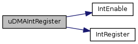
Registers an interrupt handler for the uDMA controller.

Parameters
ui32IntChannelidentifies which uDMA interrupt is to be registered.
pfnHandleris a pointer to the function to be called when the interrupt is activated.

This function registers and enables the handler to be called when the uDMA controller generates an interrupt. The ui32IntChannel parameter should be one of the following:

  • UDMA_INT_SW to register an interrupt handler to process interrupts from the uDMA software channel (UDMA_CHANNEL_SW)
  • UDMA_INT_ERR to register an interrupt handler to process uDMA error interrupts
See also
IntRegister() for important information about registering interrupt handlers.
Note
The interrupt handler for the uDMA is for transfer completion when the channel UDMA_CHANNEL_SW is used and for error interrupts. The interrupts for each peripheral channel are handled through the individual peripheral interrupt handlers.
Returns
None.

Definition at line 1092 of file udma.c.

References ASSERT, IntEnable(), IntRegister(), UDMA_INT_ERR, and UDMA_INT_SW.

1093 {
1094  //
1095  // Check the arguments.
1096  //
1097  ASSERT(pfnHandler);
1098  ASSERT((ui32IntChannel == UDMA_INT_SW) ||
1099  (ui32IntChannel == UDMA_INT_ERR));
1100 
1101  //
1102  // Register the interrupt handler.
1103  //
1104  IntRegister(ui32IntChannel, pfnHandler);
1105 
1106  //
1107  // Enable the memory management fault.
1108  //
1109  IntEnable(ui32IntChannel);
1110 }
#define ASSERT(expr)
Definition: debug.h:67
#define UDMA_INT_SW
Definition: udma.h:299
#define UDMA_INT_ERR
Definition: udma.h:300
void IntRegister(uint32_t ui32Interrupt, void(*pfnHandler)(void))
Definition: interrupt.c:309
void IntEnable(uint32_t ui32Interrupt)
Definition: interrupt.c:610

Here is the call graph for this function:

uint32_t uDMAIntStatus ( void  )

Gets the uDMA controller channel interrupt status.

This function is used to get the interrupt status of the uDMA controller. The returned value is a 32-bit bit mask that indicates which channels are requesting an interrupt. This function can be used from within an interrupt handler to determine or confirm which uDMA channel has requested an interrupt.

Note
This function is only available on devices that have the DMA Channel Interrupt Status Register (DMACHIS). Please consult the data sheet for your part.
Returns
Returns a 32-bit mask which indicates requesting uDMA channels. There is a bit for each channel and a 1 indicates that the channel is requesting an interrupt. Multiple bits can be set.

Definition at line 1163 of file udma.c.

References HWREG, and UDMA_CHIS.

1164 {
1165  //
1166  // Return the value of the uDMA interrupt status register
1167  //
1168  return(HWREG(UDMA_CHIS));
1169 }
#define HWREG(x)
Definition: hw_types.h:48
#define UDMA_CHIS
Definition: hw_udma.h:71
void uDMAIntUnregister ( uint32_t  ui32IntChannel)

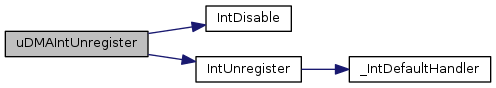
Unregisters an interrupt handler for the uDMA controller.

Parameters
ui32IntChannelidentifies which uDMA interrupt to unregister.

This function disables and unregisters the handler to be called for the specified uDMA interrupt. The ui32IntChannel parameter should be one of UDMA_INT_SW or UDMA_INT_ERR as documented for the function uDMAIntRegister().

See also
IntRegister() for important information about registering interrupt handlers.
Returns
None.

Definition at line 1130 of file udma.c.

References IntDisable(), and IntUnregister().

1131 {
1132  //
1133  // Disable the interrupt.
1134  //
1135  IntDisable(ui32IntChannel);
1136 
1137  //
1138  // Unregister the interrupt handler.
1139  //
1140  IntUnregister(ui32IntChannel);
1141 }
void IntUnregister(uint32_t ui32Interrupt)
Definition: interrupt.c:381
void IntDisable(uint32_t ui32Interrupt)
Definition: interrupt.c:684

Here is the call graph for this function: