|
EE445M RTOS
Taken at the University of Texas Spring 2015
|
|
EE445M RTOS
Taken at the University of Texas Spring 2015
|
#include <lcd.h>
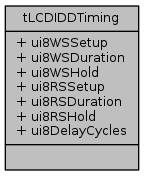
Data Fields | |
| uint8_t | ui8WSSetup |
| uint8_t | ui8WSDuration |
| uint8_t | ui8WSHold |
| uint8_t | ui8RSSetup |
| uint8_t | ui8RSDuration |
| uint8_t | ui8RSHold |
| uint8_t | ui8DelayCycles |
A structure containing timing parameters for the LIDD (LCD Interface Display Driver) interface. This is used with the LCDIDDTimingSet function.
| uint8_t tLCDIDDTiming::ui8DelayCycles |
Field value defines the number of MCLK cycles between the end of one device access and the start of another device access using the same Chip Select unless the two accesses are both Reads. In this case, this delay is not incurred. Valid vales are from 1 to 4.
Definition at line 164 of file lcd.h.
Referenced by LCDIDDTimingSet().
| uint8_t tLCDIDDTiming::ui8RSDuration |
Read Strobe Duration cycles. Field value defines the number of MCLK cycles for which the Read Strobe is held active when performing a read access. Valid values are from 1 to 63.
Definition at line 148 of file lcd.h.
Referenced by LCDIDDTimingSet().
| uint8_t tLCDIDDTiming::ui8RSHold |
Read Strobe Hold cycles. Field value defines the number of MCLK cycles for which Data Bus/Pad Output Enable, ALE, the Direction bit, and Chip Select are held after the Read Strobe is deasserted when performing a read access. Valid values are from 1 to 15.
Definition at line 156 of file lcd.h.
Referenced by LCDIDDTimingSet().
| uint8_t tLCDIDDTiming::ui8RSSetup |
Read Strobe Set-Up cycles. When performing a read access, this field defines the number of MCLK cycles that Data Bus/Pad Output Enable, ALE, the Direction bit, and Chip Select have to be ready before the Read Strobe is asserted. Valid values are from 0 to 31.
Definition at line 141 of file lcd.h.
Referenced by LCDIDDTimingSet().
| uint8_t tLCDIDDTiming::ui8WSDuration |
Write Strobe Duration cycles. Field value defines the number of MCLK cycles for which the Write Strobe is held active when performing a write access. Valid values are from 1 to 63.
Definition at line 125 of file lcd.h.
Referenced by LCDIDDTimingSet().
| uint8_t tLCDIDDTiming::ui8WSHold |
Write Strobe Hold cycles. Field value defines the number of MCLK cycles for which Data Bus/Pad Output Enable, ALE, the Direction bit, and Chip Select are held after the Write Strobe is deasserted when performing a write access. Valid values are from 1 to 15.
Definition at line 133 of file lcd.h.
Referenced by LCDIDDTimingSet().
| uint8_t tLCDIDDTiming::ui8WSSetup |
Write Strobe Set-Up cycles. When performing a write access, this field defines the number of MCLK cycles that Data Bus/Pad Output Enable, ALE, the Direction bit, and Chip Select have to be ready before the Write Strobe is asserted. Valid values are from 0 to 31.
Definition at line 118 of file lcd.h.
Referenced by LCDIDDTimingSet().
 1.8.9.1
