|
EE445M RTOS
Taken at the University of Texas Spring 2015
|
|
EE445M RTOS
Taken at the University of Texas Spring 2015
|
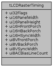
#include <lcd.h>
Data Fields | |
| uint32_t | ui32Flags |
| uint16_t | ui16PanelWidth |
| uint16_t | ui16PanelHeight |
| uint16_t | ui16HFrontPorch |
| uint16_t | ui16HBackPorch |
| uint16_t | ui16HSyncWidth |
| uint8_t | ui8VFrontPorch |
| uint8_t | ui8VBackPorch |
| uint8_t | ui8VSyncWidth |
| uint8_t | ui8ACBiasLineCount |
A structure containing timing parameters for the raster interface. This is used with the LCDRasterTimingSet function.
| uint16_t tLCDRasterTiming::ui16HBackPorch |
A value from 1 to 1024 that specifies the number of pixel clock periods to add to the beginning of a line before active video is asserted.
Definition at line 230 of file lcd.h.
Referenced by LCDRasterTimingSet().
| uint16_t tLCDRasterTiming::ui16HFrontPorch |
A value from 1 to 1024 that specifies the number of pixel clock periods to add to the end of each line after active video has ended.
Definition at line 224 of file lcd.h.
Referenced by LCDRasterTimingSet().
| uint16_t tLCDRasterTiming::ui16HSyncWidth |
A value from 1 to 1024 that specifies the number of pixel clock periods to pulse the line clock at the end of each line.
Definition at line 236 of file lcd.h.
Referenced by LCDRasterTimingSet().
| uint16_t tLCDRasterTiming::ui16PanelHeight |
The number of lines on the LCD display. Valid values are from 1 to
Definition at line 218 of file lcd.h.
Referenced by LCDRasterTimingSet().
| uint16_t tLCDRasterTiming::ui16PanelWidth |
The number of pixels contained within each line on the LCD display. Valid values are multiple of 16 less than or equal to 2048.
Definition at line 212 of file lcd.h.
Referenced by LCDRasterTimingSet().
| uint32_t tLCDRasterTiming::ui32Flags |
Flags configuring the polarity and active edges of the various signals in the raster interface. This field is comprised of a logical OR of the labels with prefix ``RASTER_TIMING_''.
Definition at line 206 of file lcd.h.
Referenced by LCDRasterTimingSet().
| uint8_t tLCDRasterTiming::ui8ACBiasLineCount |
A value from 0 to 255 that specifies the number of line clocks to count before transitioning the AC Bias pin. This pin is used to periodically invert the polarity of the power supply to prevent DC charge build-up within the display.
Definition at line 270 of file lcd.h.
Referenced by LCDRasterTimingSet().
| uint8_t tLCDRasterTiming::ui8VBackPorch |
A value from 0 to 255 that specifies the number of line clock periods to add to the beginning of a frame before the first active line is output to the display.
Definition at line 249 of file lcd.h.
Referenced by LCDRasterTimingSet().
| uint8_t tLCDRasterTiming::ui8VFrontPorch |
A value from 0 to 255 that specifies the number of line clock periods to add to the end of each frame after the last active line.
Definition at line 242 of file lcd.h.
Referenced by LCDRasterTimingSet().
| uint8_t tLCDRasterTiming::ui8VSyncWidth |
In active mode, a value from 1 to 64 that specifies the number of line clock periods to set the lcd_fp pin active at the end of each frame after the vertical front porch period elapses. The number of The frame clock is used as the VSYNC signal in active mode.
In passive mode, a value from 1 to 64 that specifies the number of extra line clock periods to insert after the vertical front porch period has elapsed. Note that the width of lcd_fp is not affected by this value in passive mode.
Definition at line 262 of file lcd.h.
Referenced by LCDRasterTimingSet().
 1.8.9.1
