|
EE445M RTOS
Taken at the University of Texas Spring 2015
|
|
EE445M RTOS
Taken at the University of Texas Spring 2015
|
Macros | |
| #define | UART_CLK_DIVIDER 8 |
Functions | |
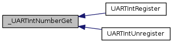
| static uint32_t | _UARTIntNumberGet (uint32_t ui32Base) |
| void | UARTParityModeSet (uint32_t ui32Base, uint32_t ui32Parity) |
| uint32_t | UARTParityModeGet (uint32_t ui32Base) |
| void | UARTFIFOLevelSet (uint32_t ui32Base, uint32_t ui32TxLevel, uint32_t ui32RxLevel) |
| void | UARTFIFOLevelGet (uint32_t ui32Base, uint32_t *pui32TxLevel, uint32_t *pui32RxLevel) |
| void | UARTConfigSetExpClk (uint32_t ui32Base, uint32_t ui32UARTClk, uint32_t ui32Baud, uint32_t ui32Config) |
| void | UARTConfigGetExpClk (uint32_t ui32Base, uint32_t ui32UARTClk, uint32_t *pui32Baud, uint32_t *pui32Config) |
| void | UARTEnable (uint32_t ui32Base) |
| void | UARTDisable (uint32_t ui32Base) |
| void | UARTFIFOEnable (uint32_t ui32Base) |
| void | UARTFIFODisable (uint32_t ui32Base) |
| void | UARTEnableSIR (uint32_t ui32Base, bool bLowPower) |
| void | UARTDisableSIR (uint32_t ui32Base) |
| void | UARTSmartCardEnable (uint32_t ui32Base) |
| void | UARTSmartCardDisable (uint32_t ui32Base) |
| void | UARTModemControlSet (uint32_t ui32Base, uint32_t ui32Control) |
| void | UARTModemControlClear (uint32_t ui32Base, uint32_t ui32Control) |
| uint32_t | UARTModemControlGet (uint32_t ui32Base) |
| uint32_t | UARTModemStatusGet (uint32_t ui32Base) |
| void | UARTFlowControlSet (uint32_t ui32Base, uint32_t ui32Mode) |
| uint32_t | UARTFlowControlGet (uint32_t ui32Base) |
| void | UARTTxIntModeSet (uint32_t ui32Base, uint32_t ui32Mode) |
| uint32_t | UARTTxIntModeGet (uint32_t ui32Base) |
| bool | UARTCharsAvail (uint32_t ui32Base) |
| bool | UARTSpaceAvail (uint32_t ui32Base) |
| int32_t | UARTCharGetNonBlocking (uint32_t ui32Base) |
| int32_t | UARTCharGet (uint32_t ui32Base) |
| bool | UARTCharPutNonBlocking (uint32_t ui32Base, unsigned char ucData) |
| void | UARTCharPut (uint32_t ui32Base, unsigned char ucData) |
| void | UARTBreakCtl (uint32_t ui32Base, bool bBreakState) |
| bool | UARTBusy (uint32_t ui32Base) |
| void | UARTIntRegister (uint32_t ui32Base, void(*pfnHandler)(void)) |
| void | UARTIntUnregister (uint32_t ui32Base) |
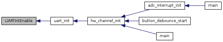
| void | UARTIntEnable (uint32_t ui32Base, uint32_t ui32IntFlags) |
| void | UARTIntDisable (uint32_t ui32Base, uint32_t ui32IntFlags) |
| uint32_t | UARTIntStatus (uint32_t ui32Base, bool bMasked) |
| void | UARTIntClear (uint32_t ui32Base, uint32_t ui32IntFlags) |
| void | UARTDMAEnable (uint32_t ui32Base, uint32_t ui32DMAFlags) |
| void | UARTDMADisable (uint32_t ui32Base, uint32_t ui32DMAFlags) |
| uint32_t | UARTRxErrorGet (uint32_t ui32Base) |
| void | UARTRxErrorClear (uint32_t ui32Base) |
| void | UARTClockSourceSet (uint32_t ui32Base, uint32_t ui32Source) |
| uint32_t | UARTClockSourceGet (uint32_t ui32Base) |
| void | UART9BitEnable (uint32_t ui32Base) |
| void | UART9BitDisable (uint32_t ui32Base) |
| void | UART9BitAddrSet (uint32_t ui32Base, uint8_t ui8Addr, uint8_t ui8Mask) |
| void | UART9BitAddrSend (uint32_t ui32Base, uint8_t ui8Addr) |
Variables | |
| static const uint32_t | g_ppui32UARTIntMap [][2] |
| static const uint_fast8_t | g_ui8UARTIntMapRows |
| static const uint32_t | g_ppui32UARTIntMapSnowflake [][2] |
| static const uint_fast8_t | g_ui8UARTIntMapRowsSnowflake |
| #define UART_CLK_DIVIDER 8 |
Definition at line 64 of file uart.c.
Referenced by UARTConfigSetExpClk().
|
static |
Definition at line 137 of file uart.c.
References CLASS_IS_TM4C129, g_ppui32UARTIntMap, g_ppui32UARTIntMapSnowflake, g_ui8UARTIntMapRows, and g_ui8UARTIntMapRowsSnowflake.
Referenced by UARTIntRegister(), and UARTIntUnregister().
| void UART9BitAddrSend | ( | uint32_t | ui32Base, |
| uint8_t | ui8Addr | ||
| ) |
Sends an address character from the specified port when operating in 9-bit mode.
| ui32Base | is the base address of the UART port. |
| ui8Addr | is the address to be transmitted. |
This function waits until all data has been sent from the specified port and then sends the given address as an address byte. It then waits until the address byte has been transmitted before returning.
The normal data functions (UARTCharPut(), UARTCharPutNonBlocking(), UARTCharGet(), and UARTCharGetNonBlocking()) are used to send and receive data characters in 9-bit mode.
Definition at line 1910 of file uart.c.
References ASSERT, HWREG, UART_FR_BUSY, UART_FR_TXFE, UART_LCRH_EPS, UART_LCRH_PEN, UART_LCRH_SPS, UART_O_DR, UART_O_FR, and UART_O_LCRH.
| void UART9BitAddrSet | ( | uint32_t | ui32Base, |
| uint8_t | ui8Addr, | ||
| uint8_t | ui8Mask | ||
| ) |
Sets the device address(es) for 9-bit mode.
| ui32Base | is the base address of the UART port. |
| ui8Addr | is the device address. |
| ui8Mask | is the device address mask. |
This function configures the device address or range of device addresses that respond to requests on the 9-bit UART port. The received address is masked with the mask and then compared against the given address, allowing either a single address (if ui8Mask is 0xff) or a set of addresses to be matched.
Definition at line 1871 of file uart.c.
References ASSERT, HWREG, UART_9BITADDR_ADDR_S, UART_9BITAMASK_MASK_S, UART_O_9BITADDR, and UART_O_9BITAMASK.
| void UART9BitDisable | ( | uint32_t | ui32Base | ) |
Disables 9-bit mode on the specified UART.
| ui32Base | is the base address of the UART port. |
This function disables the 9-bit operational mode of the UART.
Definition at line 1836 of file uart.c.
References ASSERT, HWREG, UART_9BITADDR_9BITEN, and UART_O_9BITADDR.
| void UART9BitEnable | ( | uint32_t | ui32Base | ) |
Enables 9-bit mode on the specified UART.
| ui32Base | is the base address of the UART port. |
This function enables the 9-bit operational mode of the UART.
Definition at line 1807 of file uart.c.
References ASSERT, HWREG, UART_9BITADDR_9BITEN, and UART_O_9BITADDR.
| void UARTBreakCtl | ( | uint32_t | ui32Base, |
| bool | bBreakState | ||
| ) |
Causes a BREAK to be sent.
| ui32Base | is the base address of the UART port. |
| bBreakState | controls the output level. |
Calling this function with bBreakState set to true asserts a break condition on the UART. Calling this function with bBreakState set to false removes the break condition. For proper transmission of a break command, the break must be asserted for at least two complete frames.
Definition at line 1304 of file uart.c.
References ASSERT, HWREG, UART_LCRH_BRK, and UART_O_LCRH.
| bool UARTBusy | ( | uint32_t | ui32Base | ) |
Determines whether the UART transmitter is busy or not.
| ui32Base | is the base address of the UART port. |
This function allows the caller to determine whether all transmitted bytes have cleared the transmitter hardware. If false is returned, the transmit FIFO is empty and all bits of the last transmitted character, including all stop bits, have left the hardware shift register.
Definition at line 1336 of file uart.c.
References ASSERT, HWREG, UART_FR_BUSY, and UART_O_FR.
| int32_t UARTCharGet | ( | uint32_t | ui32Base | ) |
Waits for a character from the specified port.
| ui32Base | is the base address of the UART port. |
This function gets a character from the receive FIFO for the specified port. If there are no characters available, this function waits until a character is received before returning.
Definition at line 1184 of file uart.c.
References ASSERT, HWREG, UART_FR_RXFE, UART_O_DR, and UART_O_FR.
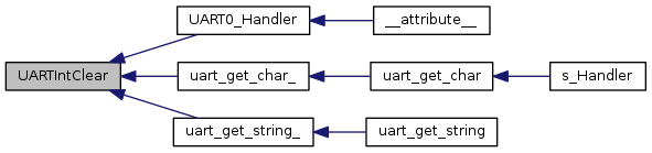
Referenced by uart_get_string_().

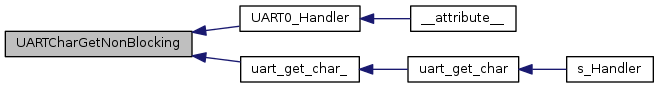
| int32_t UARTCharGetNonBlocking | ( | uint32_t | ui32Base | ) |
Receives a character from the specified port.
| ui32Base | is the base address of the UART port. |
This function gets a character from the receive FIFO for the specified port.
Definition at line 1143 of file uart.c.
References ASSERT, HWREG, UART_FR_RXFE, UART_O_DR, and UART_O_FR.
Referenced by UART0_Handler(), and uart_get_char_().
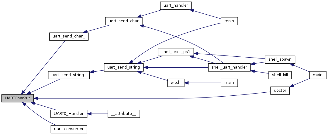
| void UARTCharPut | ( | uint32_t | ui32Base, |
| unsigned char | ucData | ||
| ) |
Waits to send a character from the specified port.
| ui32Base | is the base address of the UART port. |
| ucData | is the character to be transmitted. |
This function sends the character ucData to the transmit FIFO for the specified port. If there is no space available in the transmit FIFO, this function waits until there is space available before returning.
Definition at line 1268 of file uart.c.
References ASSERT, HWREG, UART_FR_TXFF, UART_O_DR, and UART_O_FR.
Referenced by doctor(), UART0_Handler(), uart_consumer(), uart_send_char_(), and uart_send_string_().
| bool UARTCharPutNonBlocking | ( | uint32_t | ui32Base, |
| unsigned char | ucData | ||
| ) |
Sends a character to the specified port.
| ui32Base | is the base address of the UART port. |
| ucData | is the character to be transmitted. |
This function writes the character ucData to the transmit FIFO for the specified port. This function does not block, so if there is no space available, then a false is returned and the application must retry the function later.
Definition at line 1222 of file uart.c.
References ASSERT, HWREG, UART_FR_TXFF, UART_O_DR, and UART_O_FR.
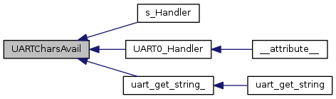
| bool UARTCharsAvail | ( | uint32_t | ui32Base | ) |
Determines if there are any characters in the receive FIFO.
| ui32Base | is the base address of the UART port. |
This function returns a flag indicating whether or not there is data available in the receive FIFO.
Definition at line 1087 of file uart.c.
References ASSERT, HWREG, UART_FR_RXFE, and UART_O_FR.
Referenced by s_Handler(), UART0_Handler(), and uart_get_string_().
| uint32_t UARTClockSourceGet | ( | uint32_t | ui32Base | ) |
Gets the baud clock source for the specified UART.
| ui32Base | is the base address of the UART port. |
This function returns the baud clock source for the specified UART. The possible baud clock source are the system clock (UART_CLOCK_SYSTEM) or the precision internal oscillator (UART_CLOCK_PIOSC).
Definition at line 1778 of file uart.c.
References ASSERT, HWREG, and UART_O_CC.
| void UARTClockSourceSet | ( | uint32_t | ui32Base, |
| uint32_t | ui32Source | ||
| ) |
Sets the baud clock source for the specified UART.
| ui32Base | is the base address of the UART port. |
| ui32Source | is the baud clock source for the UART. |
This function allows the baud clock source for the UART to be selected. The possible clock source are the system clock (UART_CLOCK_SYSTEM) or the precision internal oscillator (UART_CLOCK_PIOSC).
Changing the baud clock source changes the baud rate generated by the UART. Therefore, the baud rate should be reconfigured after any change to the baud clock source.
Definition at line 1745 of file uart.c.
References ASSERT, HWREG, UART_CLOCK_PIOSC, UART_CLOCK_SYSTEM, and UART_O_CC.
| void UARTConfigGetExpClk | ( | uint32_t | ui32Base, |
| uint32_t | ui32UARTClk, | ||
| uint32_t * | pui32Baud, | ||
| uint32_t * | pui32Config | ||
| ) |
Gets the current configuration of a UART.
| ui32Base | is the base address of the UART port. |
| ui32UARTClk | is the rate of the clock supplied to the UART module. |
| pui32Baud | is a pointer to storage for the baud rate. |
| pui32Config | is a pointer to storage for the data format. |
This function determines the baud rate and data format for the UART, given an explicitly provided peripheral clock (hence the ExpClk suffix). The returned baud rate is the actual baud rate; it may not be the exact baud rate requested or an ``official'' baud rate. The data format returned in pui32Config is enumerated the same as the ui32Config parameter of UARTConfigSetExpClk().
The peripheral clock is the same as the processor clock. The frequency of the system clock is the value returned by SysCtlClockGet(), or it can be explicitly hard coded if it is constant and known (to save the code/execution overhead of a call to SysCtlClockGet()).
For Tiva parts that have the ability to specify the UART baud clock source (via UARTClockSourceSet()), the peripheral clock can be changed to PIOSC. In this case, the peripheral clock should be specified as 16,000,000 (the nominal rate of PIOSC).
Definition at line 467 of file uart.c.
References ASSERT, HWREG, UART_CTL_HSE, UART_LCRH_EPS, UART_LCRH_PEN, UART_LCRH_SPS, UART_LCRH_STP2, UART_LCRH_WLEN_M, UART_O_CTL, UART_O_FBRD, UART_O_IBRD, and UART_O_LCRH.
| void UARTConfigSetExpClk | ( | uint32_t | ui32Base, |
| uint32_t | ui32UARTClk, | ||
| uint32_t | ui32Baud, | ||
| uint32_t | ui32Config | ||
| ) |
Sets the configuration of a UART.
| ui32Base | is the base address of the UART port. |
| ui32UARTClk | is the rate of the clock supplied to the UART module. |
| ui32Baud | is the desired baud rate. |
| ui32Config | is the data format for the port (number of data bits, number of stop bits, and parity). |
This function configures the UART for operation in the specified data format. The baud rate is provided in the ui32Baud parameter and the data format in the ui32Config parameter.
The ui32Config parameter is the logical OR of three values: the number of data bits, the number of stop bits, and the parity. UART_CONFIG_WLEN_8, UART_CONFIG_WLEN_7, UART_CONFIG_WLEN_6, and UART_CONFIG_WLEN_5 select from eight to five data bits per byte (respectively). UART_CONFIG_STOP_ONE and UART_CONFIG_STOP_TWO select one or two stop bits (respectively). UART_CONFIG_PAR_NONE, UART_CONFIG_PAR_EVEN, UART_CONFIG_PAR_ODD, UART_CONFIG_PAR_ONE, and UART_CONFIG_PAR_ZERO select the parity mode (no parity bit, even parity bit, odd parity bit, parity bit always one, and parity bit always zero, respectively).
The peripheral clock is the same as the processor clock. The frequency of the system clock is the value returned by SysCtlClockGet(), or it can be explicitly hard coded if it is constant and known (to save the code/execution overhead of a call to SysCtlClockGet()).
For Tiva parts that have the ability to specify the UART baud clock source (via UARTClockSourceSet()), the peripheral clock can be changed to PIOSC. In this case, the peripheral clock should be specified as 16,000,000 (the nominal rate of PIOSC).
Definition at line 368 of file uart.c.
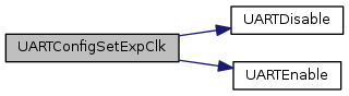
References ASSERT, HWREG, UART_CLK_DIVIDER, UART_CTL_HSE, UART_O_CTL, UART_O_FBRD, UART_O_FR, UART_O_IBRD, UART_O_LCRH, UARTDisable(), and UARTEnable().
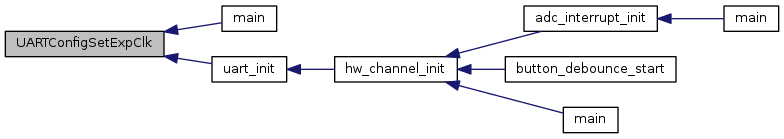
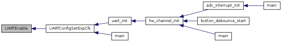
Referenced by main(), and uart_init().
| void UARTDisable | ( | uint32_t | ui32Base | ) |
Disables transmitting and receiving.
| ui32Base | is the base address of the UART port. |
This function disables the UART, waits for the end of transmission of the current character, and flushes the transmit FIFO.
Definition at line 548 of file uart.c.
References ASSERT, HWREG, UART_CTL_RXE, UART_CTL_TXE, UART_CTL_UARTEN, UART_FR_BUSY, UART_LCRH_FEN, UART_O_CTL, UART_O_FR, and UART_O_LCRH.
Referenced by UARTConfigSetExpClk().

| void UARTDisableSIR | ( | uint32_t | ui32Base | ) |
Disables SIR (IrDA) mode on the specified UART.
| ui32Base | is the base address of the UART port. |
This function disables SIR(IrDA) mode on the UART. This function only has an effect if the UART has not been enabled by a call to UARTEnable(). The call UARTEnableSIR() must be made before a call to UARTConfigSetExpClk() because the UARTConfigSetExpClk() function calls the UARTEnable() function. Another option is to call UARTDisable() followed by UARTEnableSIR() and then enable the UART by calling UARTEnable().
Definition at line 688 of file uart.c.
References ASSERT, HWREG, UART_CTL_SIREN, UART_CTL_SIRLP, and UART_O_CTL.
| void UARTDMADisable | ( | uint32_t | ui32Base, |
| uint32_t | ui32DMAFlags | ||
| ) |
Disable UART uDMA operation.
| ui32Base | is the base address of the UART port. |
| ui32DMAFlags | is a bit mask of the uDMA features to disable. |
This function is used to disable UART uDMA features that were enabled by UARTDMAEnable(). The specified UART uDMA features are disabled. The ui32DMAFlags parameter is the logical OR of any of the following values:
Definition at line 1649 of file uart.c.
References ASSERT, HWREG, and UART_O_DMACTL.
| void UARTDMAEnable | ( | uint32_t | ui32Base, |
| uint32_t | ui32DMAFlags | ||
| ) |
Enable UART uDMA operation.
| ui32Base | is the base address of the UART port. |
| ui32DMAFlags | is a bit mask of the uDMA features to enable. |
The specified UART uDMA features are enabled. The UART can be configured to use uDMA for transmit or receive and to disable receive if an error occurs. The ui32DMAFlags parameter is the logical OR of any of the following values:
Definition at line 1617 of file uart.c.
References ASSERT, HWREG, and UART_O_DMACTL.
| void UARTEnable | ( | uint32_t | ui32Base | ) |
Enables transmitting and receiving.
| ui32Base | is the base address of the UART port. |
This function enables the UART and its transmit and receive FIFOs.
Definition at line 516 of file uart.c.
References ASSERT, HWREG, UART_CTL_RXE, UART_CTL_TXE, UART_CTL_UARTEN, UART_LCRH_FEN, UART_O_CTL, and UART_O_LCRH.
Referenced by UARTConfigSetExpClk().
| void UARTEnableSIR | ( | uint32_t | ui32Base, |
| bool | bLowPower | ||
| ) |
Enables SIR (IrDA) mode on the specified UART.
| ui32Base | is the base address of the UART port. |
| bLowPower | indicates if SIR Low Power Mode is to be used. |
This function enables SIR (IrDA) mode on the UART. If the bLowPower flag is set, then SIR low power mode will be selected as well. This function only has an effect if the UART has not been enabled by a call to UARTEnable(). The call UARTEnableSIR() must be made before a call to UARTConfigSetExpClk() because the UARTConfigSetExpClk() function calls the UARTEnable() function. Another option is to call UARTDisable() followed by UARTEnableSIR() and then enable the UART by calling UARTEnable().
Definition at line 647 of file uart.c.
References ASSERT, HWREG, UART_CTL_SIREN, UART_CTL_SIRLP, and UART_O_CTL.
| void UARTFIFODisable | ( | uint32_t | ui32Base | ) |
Disables the transmit and receive FIFOs.
| ui32Base | is the base address of the UART port. |
This function disables the transmit and receive FIFOs in the UART.
Definition at line 611 of file uart.c.
References ASSERT, HWREG, UART_LCRH_FEN, and UART_O_LCRH.
| void UARTFIFOEnable | ( | uint32_t | ui32Base | ) |
Enables the transmit and receive FIFOs.
| ui32Base | is the base address of the UART port. |
This functions enables the transmit and receive FIFOs in the UART.
Definition at line 586 of file uart.c.
References ASSERT, HWREG, UART_LCRH_FEN, and UART_O_LCRH.
| void UARTFIFOLevelGet | ( | uint32_t | ui32Base, |
| uint32_t * | pui32TxLevel, | ||
| uint32_t * | pui32RxLevel | ||
| ) |
Gets the FIFO level at which interrupts are generated.
| ui32Base | is the base address of the UART port. |
| pui32TxLevel | is a pointer to storage for the transmit FIFO level, returned as one of UART_FIFO_TX1_8, UART_FIFO_TX2_8, UART_FIFO_TX4_8, UART_FIFO_TX6_8, or UART_FIFO_TX7_8. |
| pui32RxLevel | is a pointer to storage for the receive FIFO level, returned as one of UART_FIFO_RX1_8, UART_FIFO_RX2_8, UART_FIFO_RX4_8, UART_FIFO_RX6_8, or UART_FIFO_RX7_8. |
This function gets the FIFO level at which transmit and receive interrupts are generated.
Definition at line 307 of file uart.c.
References ASSERT, HWREG, UART_IFLS_RX_M, UART_IFLS_TX_M, and UART_O_IFLS.
| void UARTFIFOLevelSet | ( | uint32_t | ui32Base, |
| uint32_t | ui32TxLevel, | ||
| uint32_t | ui32RxLevel | ||
| ) |
Sets the FIFO level at which interrupts are generated.
| ui32Base | is the base address of the UART port. |
| ui32TxLevel | is the transmit FIFO interrupt level, specified as one of UART_FIFO_TX1_8, UART_FIFO_TX2_8, UART_FIFO_TX4_8, UART_FIFO_TX6_8, or UART_FIFO_TX7_8. |
| ui32RxLevel | is the receive FIFO interrupt level, specified as one of UART_FIFO_RX1_8, UART_FIFO_RX2_8, UART_FIFO_RX4_8, UART_FIFO_RX6_8, or UART_FIFO_RX7_8. |
This function configures the FIFO level at which transmit and receive interrupts are generated.
Definition at line 264 of file uart.c.
References ASSERT, HWREG, UART_FIFO_RX1_8, UART_FIFO_RX2_8, UART_FIFO_RX4_8, UART_FIFO_RX6_8, UART_FIFO_RX7_8, UART_FIFO_TX1_8, UART_FIFO_TX2_8, UART_FIFO_TX4_8, UART_FIFO_TX6_8, UART_FIFO_TX7_8, and UART_O_IFLS.
| uint32_t UARTFlowControlGet | ( | uint32_t | ui32Base | ) |
Returns the UART hardware flow control mode currently in use.
| ui32Base | is the base address of the UART port. |
This function returns the current hardware flow control mode.
Definition at line 983 of file uart.c.
References ASSERT, HWREG, UART_FLOWCONTROL_RX, UART_FLOWCONTROL_TX, and UART_O_CTL.
| void UARTFlowControlSet | ( | uint32_t | ui32Base, |
| uint32_t | ui32Mode | ||
| ) |
Sets the UART hardware flow control mode to be used.
| ui32Base | is the base address of the UART port. |
| ui32Mode | indicates the flow control modes to be used. This parameter is a logical OR combination of values UART_FLOWCONTROL_TX and UART_FLOWCONTROL_RX to enable hardware transmit (CTS) and receive (RTS) flow control or UART_FLOWCONTROL_NONE to disable hardware flow control. |
This function configures the required hardware flow control modes. If ui32Mode contains flag UART_FLOWCONTROL_TX, data is only transmitted if the incoming CTS signal is asserted. If ui32Mode contains flag UART_FLOWCONTROL_RX, the RTS output is controlled by the hardware and is asserted only when there is space available in the receive FIFO. If no hardware flow control is required, UART_FLOWCONTROL_NONE should be passed.
Definition at line 947 of file uart.c.
References ASSERT, HWREG, UART_FLOWCONTROL_RX, UART_FLOWCONTROL_TX, and UART_O_CTL.
| void UARTIntClear | ( | uint32_t | ui32Base, |
| uint32_t | ui32IntFlags | ||
| ) |
Clears UART interrupt sources.
| ui32Base | is the base address of the UART port. |
| ui32IntFlags | is a bit mask of the interrupt sources to be cleared. |
The specified UART interrupt sources are cleared, so that they no longer assert. This function must be called in the interrupt handler to keep the interrupt from being triggered again immediately upon exit.
The ui32IntFlags parameter has the same definition as the ui32IntFlags parameter to UARTIntEnable().
Definition at line 1581 of file uart.c.
References ASSERT, HWREG, and UART_O_ICR.
Referenced by UART0_Handler(), uart_get_char_(), and uart_get_string_().
| void UARTIntDisable | ( | uint32_t | ui32Base, |
| uint32_t | ui32IntFlags | ||
| ) |
Disables individual UART interrupt sources.
| ui32Base | is the base address of the UART port. |
| ui32IntFlags | is the bit mask of the interrupt sources to be disabled. |
This function disables the indicated UART interrupt sources. Only the sources that are enabled can be reflected to the processor interrupt; disabled sources have no effect on the processor.
The ui32IntFlags parameter has the same definition as the ui32IntFlags parameter to UARTIntEnable().
Definition at line 1503 of file uart.c.
References ASSERT, HWREG, and UART_O_IM.
| void UARTIntEnable | ( | uint32_t | ui32Base, |
| uint32_t | ui32IntFlags | ||
| ) |
Enables individual UART interrupt sources.
| ui32Base | is the base address of the UART port. |
| ui32IntFlags | is the bit mask of the interrupt sources to be enabled. |
This function enables the indicated UART interrupt sources. Only the sources that are enabled can be reflected to the processor interrupt; disabled sources have no effect on the processor.
The ui32IntFlags parameter is the logical OR of any of the following:
Definition at line 1471 of file uart.c.
References ASSERT, HWREG, and UART_O_IM.
Referenced by uart_init().
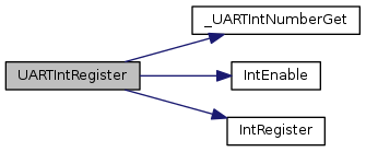
| void UARTIntRegister | ( | uint32_t | ui32Base, |
| void(*)(void) | pfnHandler | ||
| ) |
Registers an interrupt handler for a UART interrupt.
| ui32Base | is the base address of the UART port. |
| pfnHandler | is a pointer to the function to be called when the UART interrupt occurs. |
This function does the actual registering of the interrupt handler. This function enables the global interrupt in the interrupt controller; specific UART interrupts must be enabled via UARTIntEnable(). It is the interrupt handler's responsibility to clear the interrupt source.
Definition at line 1369 of file uart.c.
References _UARTIntNumberGet(), ASSERT, IntEnable(), and IntRegister().
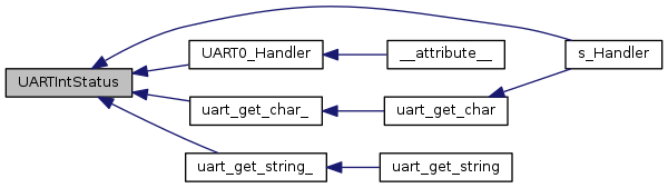
| uint32_t UARTIntStatus | ( | uint32_t | ui32Base, |
| bool | bMasked | ||
| ) |
Gets the current interrupt status.
| ui32Base | is the base address of the UART port. |
| bMasked | is false if the raw interrupt status is required and true if the masked interrupt status is required. |
This function returns the interrupt status for the specified UART. Either the raw interrupt status or the status of interrupts that are allowed to reflect to the processor can be returned.
Definition at line 1533 of file uart.c.
References ASSERT, HWREG, UART_O_MIS, and UART_O_RIS.
Referenced by s_Handler(), UART0_Handler(), uart_get_char_(), and uart_get_string_().
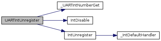
| void UARTIntUnregister | ( | uint32_t | ui32Base | ) |
Unregisters an interrupt handler for a UART interrupt.
| ui32Base | is the base address of the UART port. |
This function does the actual unregistering of the interrupt handler. It clears the handler to be called when a UART interrupt occurs. This function also masks off the interrupt in the interrupt controller so that the interrupt handler no longer is called.
Definition at line 1414 of file uart.c.
References _UARTIntNumberGet(), ASSERT, IntDisable(), and IntUnregister().
| void UARTModemControlClear | ( | uint32_t | ui32Base, |
| uint32_t | ui32Control | ||
| ) |
Clears the states of the DTR and/or RTS modem control signals.
| ui32Base | is the base address of the UART port. |
| ui32Control | is a bit-mapped flag indicating which modem control bits should be set. |
This function clears the states of the DTR or RTS modem handshake outputs from the UART.
The ui32Control parameter is the logical OR of any of the following:
Definition at line 842 of file uart.c.
References ASSERT, HWREG, UART1_BASE, UART_O_CTL, UART_OUTPUT_DTR, and UART_OUTPUT_RTS.
| uint32_t UARTModemControlGet | ( | uint32_t | ui32Base | ) |
Gets the states of the DTR and RTS modem control signals.
| ui32Base | is the base address of the UART port. |
This function returns the current states of each of the two UART modem control signals, DTR and RTS.
Definition at line 880 of file uart.c.
References ASSERT, HWREG, UART1_BASE, UART_O_CTL, UART_OUTPUT_DTR, and UART_OUTPUT_RTS.
| void UARTModemControlSet | ( | uint32_t | ui32Base, |
| uint32_t | ui32Control | ||
| ) |
Sets the states of the DTR and/or RTS modem control signals.
| ui32Base | is the base address of the UART port. |
| ui32Control | is a bit-mapped flag indicating which modem control bits should be set. |
This function configures the states of the DTR or RTS modem handshake outputs from the UART.
The ui32Control parameter is the logical OR of any of the following:
Definition at line 800 of file uart.c.
References ASSERT, HWREG, UART1_BASE, UART_O_CTL, UART_OUTPUT_DTR, and UART_OUTPUT_RTS.
| uint32_t UARTModemStatusGet | ( | uint32_t | ui32Base | ) |
Gets the states of the RI, DCD, DSR and CTS modem status signals.
| ui32Base | is the base address of the UART port. |
This function returns the current states of each of the four UART modem status signals, RI, DCD, DSR and CTS.
Definition at line 910 of file uart.c.
References ASSERT, HWREG, UART1_BASE, UART_INPUT_CTS, UART_INPUT_DCD, UART_INPUT_DSR, UART_INPUT_RI, and UART_O_FR.
| uint32_t UARTParityModeGet | ( | uint32_t | ui32Base | ) |
Gets the type of parity currently being used.
| ui32Base | is the base address of the UART port. |
This function gets the type of parity used for transmitting data and expected when receiving data.
Definition at line 231 of file uart.c.
References ASSERT, HWREG, UART_LCRH_EPS, UART_LCRH_PEN, UART_LCRH_SPS, and UART_O_LCRH.
| void UARTParityModeSet | ( | uint32_t | ui32Base, |
| uint32_t | ui32Parity | ||
| ) |
Sets the type of parity.
| ui32Base | is the base address of the UART port. |
| ui32Parity | specifies the type of parity to use. |
This function configures the type of parity to use for transmitting and expect when receiving. The ui32Parity parameter must be one of UART_CONFIG_PAR_NONE, UART_CONFIG_PAR_EVEN, UART_CONFIG_PAR_ODD, UART_CONFIG_PAR_ONE, or UART_CONFIG_PAR_ZERO. The last two parameters allow direct control of the parity bit; it is always either one or zero based on the mode.
Definition at line 196 of file uart.c.
References ASSERT, HWREG, UART_CONFIG_PAR_EVEN, UART_CONFIG_PAR_NONE, UART_CONFIG_PAR_ODD, UART_CONFIG_PAR_ONE, UART_CONFIG_PAR_ZERO, UART_LCRH_EPS, UART_LCRH_PEN, UART_LCRH_SPS, and UART_O_LCRH.
| void UARTRxErrorClear | ( | uint32_t | ui32Base | ) |
Clears all reported receiver errors.
| ui32Base | is the base address of the UART port. |
This function is used to clear all receiver error conditions reported via UARTRxErrorGet(). If using the overrun, framing error, parity error or break interrupts, this function must be called after clearing the interrupt to ensure that later errors of the same type trigger another interrupt.
Definition at line 1708 of file uart.c.
References ASSERT, HWREG, and UART_O_ECR.
| uint32_t UARTRxErrorGet | ( | uint32_t | ui32Base | ) |
Gets current receiver errors.
| ui32Base | is the base address of the UART port. |
This function returns the current state of each of the 4 receiver error sources. The returned errors are equivalent to the four error bits returned via the previous call to UARTCharGet() or UARTCharGetNonBlocking() with the exception that the overrun error is set immediately when the overrun occurs rather than when a character is next read.
Definition at line 1680 of file uart.c.
References ASSERT, HWREG, and UART_O_RSR.
| void UARTSmartCardDisable | ( | uint32_t | ui32Base | ) |
Disables ISO7816 smart card mode on the specified UART.
| ui32Base | is the base address of the UART port. |
This function clears the SMART (ISO7816 smart card) bit in the UART control register.
Definition at line 763 of file uart.c.
References ASSERT, HWREG, UART_CTL_SMART, and UART_O_CTL.
| void UARTSmartCardEnable | ( | uint32_t | ui32Base | ) |
Enables ISO7816 smart card mode on the specified UART.
| ui32Base | is the base address of the UART port. |
This function enables the SMART control bit for the ISO7816 smart card mode on the UART. This call also sets 8-bit word length and even parity as required by ISO7816.
Definition at line 719 of file uart.c.
References ASSERT, HWREG, UART_CTL_SMART, UART_LCRH_EPS, UART_LCRH_PEN, UART_LCRH_SPS, UART_LCRH_STP2, UART_LCRH_WLEN_8, UART_LCRH_WLEN_M, UART_O_CTL, and UART_O_LCRH.
| bool UARTSpaceAvail | ( | uint32_t | ui32Base | ) |
Determines if there is any space in the transmit FIFO.
| ui32Base | is the base address of the UART port. |
This function returns a flag indicating whether or not there is space available in the transmit FIFO.
Definition at line 1114 of file uart.c.
References ASSERT, HWREG, UART_FR_TXFF, and UART_O_FR.
| uint32_t UARTTxIntModeGet | ( | uint32_t | ui32Base | ) |
Returns the current operating mode for the UART transmit interrupt.
| ui32Base | is the base address of the UART port. |
This function returns the current operating mode for the UART transmit interrupt. The return value is UART_TXINT_MODE_EOT if the transmit interrupt is currently configured to be asserted once the transmitter is completely idle - the transmit FIFO is empty and all bits, including any stop bits, have cleared the transmitter. The return value is UART_TXINT_MODE_FIFO if the interrupt is configured to be asserted based on the level of the transmit FIFO.
Definition at line 1059 of file uart.c.
References ASSERT, HWREG, UART_O_CTL, UART_TXINT_MODE_EOT, and UART_TXINT_MODE_FIFO.
| void UARTTxIntModeSet | ( | uint32_t | ui32Base, |
| uint32_t | ui32Mode | ||
| ) |
Sets the operating mode for the UART transmit interrupt.
| ui32Base | is the base address of the UART port. |
| ui32Mode | is the operating mode for the transmit interrupt. It may be UART_TXINT_MODE_EOT to trigger interrupts when the transmitter is idle or UART_TXINT_MODE_FIFO to trigger based on the current transmit FIFO level. |
This function allows the mode of the UART transmit interrupt to be set. By default, the transmit interrupt is asserted when the FIFO level falls past a threshold set via a call to UARTFIFOLevelSet(). Alternatively, if this function is called with ui32Mode set to UART_TXINT_MODE_EOT, the transmit interrupt is asserted once the transmitter is completely idle - the transmit FIFO is empty and all bits, including any stop bits, have cleared the transmitter.
Definition at line 1020 of file uart.c.
References ASSERT, HWREG, UART_O_CTL, UART_TXINT_MODE_EOT, and UART_TXINT_MODE_FIFO.
|
static |
Definition at line 71 of file uart.c.
Referenced by _UARTIntNumberGet().
|
static |
Definition at line 84 of file uart.c.
Referenced by _UARTIntNumberGet().
|
static |
|
static |
Definition at line 95 of file uart.c.
Referenced by _UARTIntNumberGet().
 1.8.9.1
