|
EE445M RTOS
Taken at the University of Texas Spring 2015
|
|
EE445M RTOS
Taken at the University of Texas Spring 2015
|
Macros | |
| #define | FLASH_PP_MAINSS_S 16 |
| #define | SysCtlXtalCfgToIndex(a) ((a & 0x7c0) >> 6) |
| #define | MAX_VCO_ENTRIES 2 |
| #define | MAX_XTAL_ENTRIES 18 |
| #define | PLL_M_TO_REG(mi, mf) ((uint32_t)mi | (uint32_t)(mf << SYSCTL_PLLFREQ0_MFRAC_S)) |
| #define | PLL_N_TO_REG(n) ((uint32_t)(n - 1) << SYSCTL_PLLFREQ1_N_S) |
| #define | SYSCTL_PPBASE 0x400fe300 |
| #define | SYSCTL_SRBASE 0x400fe500 |
| #define | SYSCTL_RCGCBASE 0x400fe600 |
| #define | SYSCTL_SCGCBASE 0x400fe700 |
| #define | SYSCTL_DCGCBASE 0x400fe800 |
| #define | SYSCTL_PCBASE 0x400fe900 |
| #define | SYSCTL_PRBASE 0x400fea00 |
Functions | |
| static uint32_t | _SysCtlMemTimingGet (uint32_t ui32SysClock) |
| static uint32_t | _SysCtlFrequencyGet (uint32_t ui32Xtal) |
| uint32_t | SysCtlSRAMSizeGet (void) |
| uint32_t | SysCtlFlashSizeGet (void) |
| uint32_t | SysCtlFlashSectorSizeGet (void) |
| bool | SysCtlPeripheralPresent (uint32_t ui32Peripheral) |
| bool | SysCtlPeripheralReady (uint32_t ui32Peripheral) |
| void | SysCtlPeripheralPowerOn (uint32_t ui32Peripheral) |
| void | SysCtlPeripheralPowerOff (uint32_t ui32Peripheral) |
| void | SysCtlPeripheralReset (uint32_t ui32Peripheral) |
| void | SysCtlPeripheralEnable (uint32_t ui32Peripheral) |
| void | SysCtlPeripheralDisable (uint32_t ui32Peripheral) |
| void | SysCtlPeripheralSleepEnable (uint32_t ui32Peripheral) |
| void | SysCtlPeripheralSleepDisable (uint32_t ui32Peripheral) |
| void | SysCtlPeripheralDeepSleepEnable (uint32_t ui32Peripheral) |
| void | SysCtlPeripheralDeepSleepDisable (uint32_t ui32Peripheral) |
| void | SysCtlPeripheralClockGating (bool bEnable) |
| void | SysCtlIntRegister (void(*pfnHandler)(void)) |
| void | SysCtlIntUnregister (void) |
| void | SysCtlIntEnable (uint32_t ui32Ints) |
| void | SysCtlIntDisable (uint32_t ui32Ints) |
| void | SysCtlIntClear (uint32_t ui32Ints) |
| uint32_t | SysCtlIntStatus (bool bMasked) |
| void | SysCtlLDOSleepSet (uint32_t ui32Voltage) |
| uint32_t | SysCtlLDOSleepGet (void) |
| void | SysCtlLDODeepSleepSet (uint32_t ui32Voltage) |
| uint32_t | SysCtlLDODeepSleepGet (void) |
| void | SysCtlSleepPowerSet (uint32_t ui32Config) |
| void | SysCtlDeepSleepPowerSet (uint32_t ui32Config) |
| void | SysCtlReset (void) |
| void | SysCtlSleep (void) |
| void | SysCtlDeepSleep (void) |
| uint32_t | SysCtlResetCauseGet (void) |
| void | SysCtlResetCauseClear (uint32_t ui32Causes) |
| void | SysCtlMOSCConfigSet (uint32_t ui32Config) |
| uint32_t | SysCtlPIOSCCalibrate (uint32_t ui32Type) |
| void | SysCtlResetBehaviorSet (uint32_t ui32Behavior) |
| uint32_t | SysCtlResetBehaviorGet (void) |
| uint32_t | SysCtlClockFreqSet (uint32_t ui32Config, uint32_t ui32SysClock) |
| void | SysCtlClockSet (uint32_t ui32Config) |
| uint32_t | SysCtlClockGet (void) |
| void | SysCtlDeepSleepClockSet (uint32_t ui32Config) |
| void | SysCtlDeepSleepClockConfigSet (uint32_t ui32Div, uint32_t ui32Config) |
| void | SysCtlPWMClockSet (uint32_t ui32Config) |
| uint32_t | SysCtlPWMClockGet (void) |
| void | SysCtlGPIOAHBEnable (uint32_t ui32GPIOPeripheral) |
| void | SysCtlGPIOAHBDisable (uint32_t ui32GPIOPeripheral) |
| void | SysCtlUSBPLLEnable (void) |
| void | SysCtlUSBPLLDisable (void) |
| void | SysCtlVoltageEventConfig (uint32_t ui32Config) |
| uint32_t | SysCtlVoltageEventStatus (void) |
| void | SysCtlVoltageEventClear (uint32_t ui32Status) |
| uint32_t | SysCtlNMIStatus (void) |
| void | SysCtlNMIClear (uint32_t ui32Ints) |
| void | SysCtlClockOutConfig (uint32_t ui32Config, uint32_t ui32Div) |
| void | SysCtlAltClkConfig (uint32_t ui32Config) |
Variables | |
| static const uint32_t | g_pui32Xtals [] |
| static const uint32_t | g_pppui32XTALtoVCO [2][18][2] |
| struct { | |
| uint32_t ui32Frequency | |
| uint32_t ui32MemTiming | |
| } | g_sXTALtoMEMTIM [] |
| static const uint32_t | g_pui32VCOFrequencies [2] |
| #define FLASH_PP_MAINSS_S 16 |
Definition at line 65 of file sysctl.c.
Referenced by SysCtlFlashSectorSizeGet().
| #define MAX_VCO_ENTRIES 2 |
Definition at line 118 of file sysctl.c.
Referenced by SysCtlClockFreqSet().
| #define PLL_M_TO_REG | ( | mi, | |
| mf | |||
| ) | ((uint32_t)mi | (uint32_t)(mf << SYSCTL_PLLFREQ0_MFRAC_S)) |
| #define PLL_N_TO_REG | ( | n | ) | ((uint32_t)(n - 1) << SYSCTL_PLLFREQ1_N_S) |
| #define SYSCTL_DCGCBASE 0x400fe800 |
Definition at line 345 of file sysctl.c.
Referenced by SysCtlPeripheralDeepSleepDisable(), and SysCtlPeripheralDeepSleepEnable().
| #define SYSCTL_PCBASE 0x400fe900 |
Definition at line 346 of file sysctl.c.
Referenced by SysCtlPeripheralPowerOff(), and SysCtlPeripheralPowerOn().
| #define SYSCTL_PPBASE 0x400fe300 |
Definition at line 341 of file sysctl.c.
Referenced by SysCtlPeripheralPresent().
| #define SYSCTL_PRBASE 0x400fea00 |
Definition at line 347 of file sysctl.c.
Referenced by SysCtlPeripheralReady().
| #define SYSCTL_RCGCBASE 0x400fe600 |
Definition at line 343 of file sysctl.c.
Referenced by SysCtlPeripheralDisable(), and SysCtlPeripheralEnable().
| #define SYSCTL_SCGCBASE 0x400fe700 |
Definition at line 344 of file sysctl.c.
Referenced by SysCtlPeripheralSleepDisable(), and SysCtlPeripheralSleepEnable().
| #define SYSCTL_SRBASE 0x400fe500 |
Definition at line 342 of file sysctl.c.
Referenced by SysCtlPeripheralReset().
| #define SysCtlXtalCfgToIndex | ( | a | ) | ((a & 0x7c0) >> 6) |
Definition at line 74 of file sysctl.c.
Referenced by SysCtlClockFreqSet().
|
static |
Definition at line 266 of file sysctl.c.
References HWREG, SYSCTL_PLLFREQ0, SYSCTL_PLLFREQ0_MFRAC_M, SYSCTL_PLLFREQ0_MFRAC_S, SYSCTL_PLLFREQ0_MINT_M, SYSCTL_PLLFREQ1, SYSCTL_PLLFREQ1_N_M, SYSCTL_PLLFREQ1_N_S, SYSCTL_PLLFREQ1_Q_M, and SYSCTL_PLLFREQ1_Q_S.
Referenced by SysCtlClockFreqSet().

|
static |
Definition at line 227 of file sysctl.c.
References g_sXTALtoMEMTIM, ui32Frequency, and ui32MemTiming.
Referenced by SysCtlClockFreqSet().

| void SysCtlAltClkConfig | ( | uint32_t | ui32Config | ) |
Configures the alternate peripheral clock source.
| ui32Config | holds the configuration options for the alternate peripheral clock. |
This function configures the alternate peripheral clock. The alternate peripheral clock is used to provide a known clock in all operating modes to peripherals that support using the alternate peripheral clock as an input clock. The ui32Config parameter value provides the clock input source using one of the following values:
Example: Select the Hibernate module RTC clock as the alternate clock source.
//!
//! //
//! // Select the Hibernate module RTC clock as the alternate clock source.
//! //
//! SysCtlAltClkConfig(SYSCTL_ALTCLK_RTCOSC);
//!
\note The availability of the alternate peripheral clock varies with the
Tiva part in use.  Please consult the data sheet for the part you are
using to determine which interrupt sources are available.

\return None.
Definition at line 3686 of file sysctl.c.
References HWREG, and SYSCTL_ALTCLKCFG.
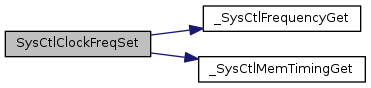
| uint32_t SysCtlClockFreqSet | ( | uint32_t | ui32Config, |
| uint32_t | ui32SysClock | ||
| ) |
Configures the system clock.
| ui32Config | is the required configuration of the device clocking. |
| ui32SysClock | is the requested processor frequency. |
This function configures the main system clocking for the device. The input frequency, oscillator source, whether or not to enable the PLL, and the system clock divider are all configured with this function. This function configures the system frequency to the closest available divisor of one of the fixed PLL VCO settings provided in the ui32Config parameter. The caller sets the ui32SysClock parameter to request the system clock frequency, and this function then attempts to match this using the values provided in the ui32Config parameter. If this function cannot exactly match the requested frequency, it picks the closest frequency that is lower than the requested frequency. The ui32Config parameter provides the remaining configuration options using a set of defines that are a logical OR of several different values, many of which are grouped into sets where only one of the set can be chosen. This function returns the current system frequency which may not match the requested frequency.
The oscillator source is chosen with one of the following values:
The system clock source is chosen with one of the following values:
The PLL VCO frequency is chosen with one of the the following values:
Example: Configure the system clocking to be 40 MHz with a 320-MHz PLL setting using the 16-MHz internal oscillator.
//! SysCtlClockFreqSet(SYSCTL_OSC_INT | SYSCTL_USE_PLL | SYSCTL_CFG_VCO_320,
//!                    40000000);
//!
\note This function cannot be used with TM4C123 devices.  For TM4C123
devices use the SysCtlClockSet() function.

\return The actual configured system clock frequency in Hz or zero if the
value could not be changed due to a parameter error or PLL lock failure.
Definition at line 2115 of file sysctl.c.
References _SysCtlFrequencyGet(), _SysCtlMemTimingGet(), ASSERT, CLASS_IS_TM4C123, g_pppui32XTALtoVCO, g_pui32Xtals, HWREG, MAX_VCO_ENTRIES, SYSCTL_MEMTIM0, SYSCTL_MOSCCTL, SYSCTL_MOSCCTL_NOXTAL, SYSCTL_MOSCCTL_OSCRNG, SYSCTL_MOSCCTL_PWRDN, SYSCTL_OSC_EXT32, SYSCTL_OSC_INT, SYSCTL_OSC_INT30, SYSCTL_OSC_MAIN, SYSCTL_PLLFREQ0, SYSCTL_PLLFREQ0_PLLPWR, SYSCTL_PLLFREQ1, SYSCTL_PLLSTAT, SYSCTL_PLLSTAT_LOCK, SYSCTL_RSCLKCFG, SYSCTL_RSCLKCFG_MEMTIMU, SYSCTL_RSCLKCFG_NEWFREQ, SYSCTL_RSCLKCFG_OSCSRC_LFIOSC, SYSCTL_RSCLKCFG_OSCSRC_M, SYSCTL_RSCLKCFG_OSCSRC_MOSC, SYSCTL_RSCLKCFG_OSCSRC_PIOSC, SYSCTL_RSCLKCFG_OSCSRC_RTC, SYSCTL_RSCLKCFG_OSYSDIV_M, SYSCTL_RSCLKCFG_OSYSDIV_S, SYSCTL_RSCLKCFG_PLLSRC_M, SYSCTL_RSCLKCFG_PLLSRC_MOSC, SYSCTL_RSCLKCFG_PLLSRC_PIOSC, SYSCTL_RSCLKCFG_PSYSDIV_M, SYSCTL_RSCLKCFG_PSYSDIV_S, SYSCTL_RSCLKCFG_USEPLL, SYSCTL_USE_OSC, SYSCTL_USE_PLL, SYSCTL_XTAL_10MHZ, SYSCTL_XTAL_16MHZ, SYSCTL_XTAL_25MHZ, SYSCTL_XTAL_5MHZ, and SysCtlXtalCfgToIndex.
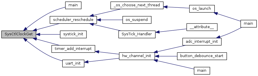
| uint32_t SysCtlClockGet | ( | void | ) |
Gets the processor clock rate.
This function determines the clock rate of the processor clock, which is also the clock rate of the peripheral modules (with the exception of PWM, which has its own clock divider; other peripherals may have different clocking, see the device data sheet for details).
Definition at line 2727 of file sysctl.c.
References ASSERT, CLASS_IS_TM4C123, g_pui32Xtals, HWREG, SYSCTL_DC1, SYSCTL_DC1_MINSYSDIV_20, SYSCTL_DC1_MINSYSDIV_25, SYSCTL_DC1_MINSYSDIV_40, SYSCTL_DC1_MINSYSDIV_50, SYSCTL_DC1_MINSYSDIV_66, SYSCTL_DC1_MINSYSDIV_80, SYSCTL_DC1_MINSYSDIV_M, SYSCTL_PLLFREQ0, SYSCTL_PLLFREQ0_MFRAC_M, SYSCTL_PLLFREQ0_MFRAC_S, SYSCTL_PLLFREQ0_MINT_M, SYSCTL_PLLFREQ0_MINT_S, SYSCTL_PLLFREQ1, SYSCTL_PLLFREQ1_N_M, SYSCTL_PLLFREQ1_N_S, SYSCTL_PLLFREQ1_Q_M, SYSCTL_PLLFREQ1_Q_S, SYSCTL_RCC, SYSCTL_RCC2, SYSCTL_RCC2_BYPASS2, SYSCTL_RCC2_DIV400, SYSCTL_RCC2_OSCSRC2_32, SYSCTL_RCC2_OSCSRC2_M, SYSCTL_RCC2_SYSDIV2_M, SYSCTL_RCC2_SYSDIV2_S, SYSCTL_RCC2_SYSDIV2LSB, SYSCTL_RCC2_USERCC2, SYSCTL_RCC_BYPASS, SYSCTL_RCC_OSCSRC_30, SYSCTL_RCC_OSCSRC_INT, SYSCTL_RCC_OSCSRC_INT4, SYSCTL_RCC_OSCSRC_M, SYSCTL_RCC_OSCSRC_MAIN, SYSCTL_RCC_SYSDIV_M, SYSCTL_RCC_SYSDIV_S, SYSCTL_RCC_USESYSDIV, SYSCTL_RCC_XTAL_M, and SYSCTL_RCC_XTAL_S.
Referenced by main(), scheduler_reschedule(), systick_init(), timer_add_interrupt(), and uart_init().
| void SysCtlClockOutConfig | ( | uint32_t | ui32Config, |
| uint32_t | ui32Div | ||
| ) |
Configures and enables or disables the clock output on the DIVSCLK pin.
| ui32Config | holds the configuration options including enabling or disabling the clock output on the DIVSCLK pin. |
| ui32Div | is the divisor for the clock selected in the ui32Config parameter. |
This function selects the source for the DIVSCLK, enables or disables the clock output and provides an output divider value. The ui32Div parameter specifies the divider for the selected clock source and has a valid range of 1-256. The ui32Config parameter configures the DIVSCLK output based on the following settings:
The first setting allows the output to be enabled or disabled.
The next group of settings selects the source for the DIVSCLK.
Example: Enable the PIOSC divided by 4 as the DIVSCLK output.
//!
//! //
//! // Enable the PIOSC divided by 4 as the DIVSCLK output.
//! //
//! SysCtlClockOutConfig(SYSCTL_DIVSCLK_EN | SYSCTL_DIVSCLK_SRC_PIOSC, 4);
//!
\note The availability of the DIVSCLK output varies with the Tiva part
in use.  Please consult the data sheet for the part you are using to
determine which interrupt sources are available.

\return None.
Definition at line 3634 of file sysctl.c.
References ASSERT, HWREG, SYSCTL_CLKOUT_DIS, SYSCTL_CLKOUT_EN, SYSCTL_CLKOUT_MOSC, SYSCTL_CLKOUT_PIOSC, SYSCTL_CLKOUT_SYSCLK, SYSCTL_DIVSCLK, and SYSCTL_DIVSCLK_DIV_M.
| void SysCtlClockSet | ( | uint32_t | ui32Config | ) |
Sets the clocking of the device.
| ui32Config | is the required configuration of the device clocking. |
This function configures the clocking of the device. The input crystal frequency, oscillator to be used, use of the PLL, and the system clock divider are all configured with this function.
The ui32Config parameter is the logical OR of several different values, many of which are grouped into sets where only one can be chosen.
The system clock divider is chosen with one of the following values: SYSCTL_SYSDIV_1, SYSCTL_SYSDIV_2, SYSCTL_SYSDIV_3, ... SYSCTL_SYSDIV_64.
The use of the PLL is chosen with either SYSCTL_USE_PLL or SYSCTL_USE_OSC.
The external crystal frequency is chosen with one of the following values: SYSCTL_XTAL_4MHZ, SYSCTL_XTAL_4_09MHZ, SYSCTL_XTAL_4_91MHZ, SYSCTL_XTAL_5MHZ, SYSCTL_XTAL_5_12MHZ, SYSCTL_XTAL_6MHZ, SYSCTL_XTAL_6_14MHZ, SYSCTL_XTAL_7_37MHZ, SYSCTL_XTAL_8MHZ, SYSCTL_XTAL_8_19MHZ, SYSCTL_XTAL_10MHZ, SYSCTL_XTAL_12MHZ, SYSCTL_XTAL_12_2MHZ, SYSCTL_XTAL_13_5MHZ, SYSCTL_XTAL_14_3MHZ, SYSCTL_XTAL_16MHZ, SYSCTL_XTAL_16_3MHZ, SYSCTL_XTAL_18MHZ, SYSCTL_XTAL_20MHZ, SYSCTL_XTAL_24MHZ, or SYSCTL_XTAL_25MHz. Values below SYSCTL_XTAL_5MHZ are not valid when the PLL is in operation.
The oscillator source is chosen with one of the following values: SYSCTL_OSC_MAIN, SYSCTL_OSC_INT, SYSCTL_OSC_INT4, SYSCTL_OSC_INT30, or SYSCTL_OSC_EXT32. SYSCTL_OSC_EXT32 is only available on devices with the hibernate module, and then only when the hibernate module has been enabled.
The internal and main oscillators are disabled with the SYSCTL_INT_OSC_DIS and SYSCTL_MAIN_OSC_DIS flags, respectively. The external oscillator must be enabled in order to use an external clock source. Note that attempts to disable the oscillator used to clock the device is prevented by the hardware.
To clock the system from an external source (such as an external crystal oscillator), use SYSCTL_USE_OSC | SYSCTL_OSC_MAIN. To clock the system from the main oscillator, use SYSCTL_USE_OSC | SYSCTL_OSC_MAIN. To clock the system from the PLL, use SYSCTL_USE_PLL | SYSCTL_OSC_MAIN, and select the appropriate crystal with one of the SYSCTL_XTAL_xxx values.
Definition at line 2532 of file sysctl.c.
References HWREG, SYSCTL_MAIN_OSC_DIS, SYSCTL_MISC, SYSCTL_MISC_MOSCPUPMIS, SYSCTL_MISC_PLLLMIS, SYSCTL_PLLSTAT, SYSCTL_PLLSTAT_LOCK, SYSCTL_RCC, SYSCTL_RCC2, SYSCTL_RCC2_BYPASS2, SYSCTL_RCC2_DIV400, SYSCTL_RCC2_OSCSRC2_M, SYSCTL_RCC2_PWRDN2, SYSCTL_RCC2_SYSDIV2_M, SYSCTL_RCC2_SYSDIV2LSB, SYSCTL_RCC2_USERCC2, SYSCTL_RCC_BYPASS, SYSCTL_RCC_MOSCDIS, SYSCTL_RCC_OSCSRC_M, SYSCTL_RCC_PWRDN, SYSCTL_RCC_SYSDIV_M, SYSCTL_RCC_USESYSDIV, SYSCTL_RCC_XTAL_M, SYSCTL_RIS, SYSCTL_RIS_MOSCPUPRIS, and SysCtlDelay().
Referenced by main().


| void SysCtlDeepSleep | ( | void | ) |
Puts the processor into deep-sleep mode.
This function places the processor into deep-sleep mode; it does not return until the processor returns to run mode. The peripherals that are enabled via SysCtlPeripheralDeepSleepEnable() continue to operate and can wake up the processor (if automatic clock gating is enabled with SysCtlPeripheralClockGating(), otherwise all peripherals continue to operate).
Definition at line 1726 of file sysctl.c.
References CPUwfi(), HWREG, NVIC_SYS_CTRL, and NVIC_SYS_CTRL_SLEEPDEEP.

| void SysCtlDeepSleepClockConfigSet | ( | uint32_t | ui32Div, |
| uint32_t | ui32Config | ||
| ) |
Sets the clock configuration of the device while in deep-sleep mode.
| ui32Div | is the clock divider when in deep-sleep mode. |
| ui32Config | is the configuration of the device clocking while in deep-sleep mode. |
This function configures the clocking of the device while in deep-sleep mode. The ui32Config parameter selects the oscillator and the ui32Div parameter sets the clock divider used in deep-sleep mode. The valid values for the ui32Div parameter range from 1 to 1024, however not all Tiva microcontrollers support this full range. This function replaces the SysCtlDeepSleepClockSet() function and can be used on Tiva devices that support deep-sleep mode.
The oscillator source is chosen from one of the following values: SYSCTL_DSLP_OSC_MAIN, SYSCTL_DSLP_OSC_INT, SYSCTL_DSLP_OSC_INT30, or SYSCTL_DSLP_OSC_EXT32. The SYSCTL_DSLP_OSC_EXT32 option is only available on devices with the hibernation module, and then only when the hibernation module is enabled.
The precision internal oscillator can be powered down in deep-sleep mode by specifying SYSCTL_DSLP_PIOSC_PD. The precision internal oscillator is not powered down if it is required for operation while in deep-sleep (based on other configuration settings).
The main oscillator can be powered down in deep-sleep mode by specifying SYSCTL_DSLP_MOSC_PD. The main oscillator is not powered down if it is required for operation while in deep-sleep (based on other configuration settings).
Definition at line 3039 of file sysctl.c.
References ASSERT, CLASS_IS_TM4C123, HWREG, SYSCTL_DSCLKCFG, SYSCTL_DSCLKCFG_DSOSCSRC_LFIOSC, SYSCTL_DSCLKCFG_DSOSCSRC_MOSC, SYSCTL_DSCLKCFG_DSOSCSRC_RTC, SYSCTL_DSCLKCFG_MOSCDPD, SYSCTL_DSCLKCFG_PIOSCPD, SYSCTL_DSLP_MOSC_PD, SYSCTL_DSLP_OSC_EXT32, SYSCTL_DSLP_OSC_INT, SYSCTL_DSLP_OSC_INT30, SYSCTL_DSLP_OSC_MAIN, SYSCTL_DSLP_PIOSC_PD, SYSCTL_DSLPCLKCFG, SYSCTL_DSLPCLKCFG_D_M, SYSCTL_DSLPCLKCFG_D_S, and SYSCTL_DSLPCLKCFG_O_M.
| void SysCtlDeepSleepClockSet | ( | uint32_t | ui32Config | ) |
Sets the clocking of the device while in deep-sleep mode.
| ui32Config | is the required configuration of the device clocking while in deep-sleep mode. |
This function configures the clocking of the device while in deep-sleep mode. The oscillator to be used and the system clock divider are configured with this function.
The ui32Config parameter is the logical OR of the following values:
The system clock divider is chosen from one of the following values: SYSCTL_DSLP_DIV_1, SYSCTL_DSLP_DIV_2, SYSCTL_DSLP_DIV_3, ... SYSCTL_DSLP_DIV_64.
The oscillator source is chosen from one of the following values: SYSCTL_DSLP_OSC_MAIN, SYSCTL_DSLP_OSC_INT, SYSCTL_DSLP_OSC_INT30, or SYSCTL_DSLP_OSC_EXT32. SYSCTL_OSC_EXT32 is only available on devices with the hibernation module, and then only when the hibernation module has been enabled.
The precision internal oscillator can be powered down in deep-sleep mode by specifying SYSCTL_DSLP_PIOSC_PD. The precision internal oscillator is not powered down if it is required for operation while in deep-sleep (based on other configuration settings.)
Definition at line 2989 of file sysctl.c.
References HWREG, and SYSCTL_DSLPCLKCFG.
| void SysCtlDeepSleepPowerSet | ( | uint32_t | ui32Config | ) |
Configures the power to the flash and SRAM while in deep-sleep mode.
| ui32Config | is the required flash and SRAM power configuration. |
This function allows the power configuration of the flash and SRAM while in deep-sleep mode to be set. The ui32Config parameter is the logical OR of the flash power configuration and the SRAM power configuration.
The flash power configuration is specified as either:
The SRAM power configuration is specified as one of:
Definition at line 1649 of file sysctl.c.
References HWREG, and SYSCTL_DSLPPWRCFG.
| uint32_t SysCtlFlashSectorSizeGet | ( | void | ) |
Gets the size of a single eraseable sector of flash.
This function determines the flash sector size on the Tiva device. This size determines the erase granularity of the device flash.
Definition at line 500 of file sysctl.c.
References CLASS_IS_TM4C129, FLASH_PP, FLASH_PP_MAINSS_M, FLASH_PP_MAINSS_S, and HWREG.
| uint32_t SysCtlFlashSizeGet | ( | void | ) |
Gets the size of the flash.
This function determines the size of the flash on the Tiva device.
Definition at line 467 of file sysctl.c.
References CLASS_IS_TM4C123, FLASH_PP, FLASH_PP_SIZE_M, HWREG, SYSCTL_DC0, and SYSCTL_DC0_FLASHSZ_M.
| void SysCtlGPIOAHBDisable | ( | uint32_t | ui32GPIOPeripheral | ) |
Disables access to a GPIO peripheral via the AHB.
| ui32GPIOPeripheral | is the GPIO peripheral to disable. |
This function disables the specified GPIO peripheral for access from the Advanced Host Bus (AHB). Once disabled, the GPIO peripheral is accessed from the legacy Advanced Peripheral Bus (APB).
The ui32GPIOPeripheral argument must be only one of the following values: SYSCTL_PERIPH_GPIOA, SYSCTL_PERIPH_GPIOB, SYSCTL_PERIPH_GPIOC, SYSCTL_PERIPH_GPIOD, SYSCTL_PERIPH_GPIOE, SYSCTL_PERIPH_GPIOF, SYSCTL_PERIPH_GPIOG, SYSCTL_PERIPH_GPIOH, or SYSCTL_PERIPH_GPIOJ.
Definition at line 3294 of file sysctl.c.
References ASSERT, HWREG, SYSCTL_GPIOHBCTL, SYSCTL_PERIPH_GPIOA, SYSCTL_PERIPH_GPIOB, SYSCTL_PERIPH_GPIOC, SYSCTL_PERIPH_GPIOD, SYSCTL_PERIPH_GPIOE, SYSCTL_PERIPH_GPIOF, SYSCTL_PERIPH_GPIOG, SYSCTL_PERIPH_GPIOH, and SYSCTL_PERIPH_GPIOJ.
| void SysCtlGPIOAHBEnable | ( | uint32_t | ui32GPIOPeripheral | ) |
Enables access to a GPIO peripheral via the AHB.
| ui32GPIOPeripheral | is the GPIO peripheral to enable. |
This function is used to enable the specified GPIO peripheral to be accessed from the Advanced Host Bus (AHB) instead of the legacy Advanced Peripheral Bus (APB). When a GPIO peripheral is enabled for AHB access, the _AHB_BASE form of the base address should be used for GPIO functions. For example, instead of using GPIO_PORTA_BASE as the base address for GPIO functions, use GPIO_PORTA_AHB_BASE instead.
The ui32GPIOPeripheral argument must be only one of the following values: SYSCTL_PERIPH_GPIOA, SYSCTL_PERIPH_GPIOB, SYSCTL_PERIPH_GPIOC, SYSCTL_PERIPH_GPIOD, SYSCTL_PERIPH_GPIOE, SYSCTL_PERIPH_GPIOF, SYSCTL_PERIPH_GPIOG, SYSCTL_PERIPH_GPIOH, or SYSCTL_PERIPH_GPIOJ.
Definition at line 3248 of file sysctl.c.
References ASSERT, HWREG, SYSCTL_GPIOHBCTL, SYSCTL_PERIPH_GPIOA, SYSCTL_PERIPH_GPIOB, SYSCTL_PERIPH_GPIOC, SYSCTL_PERIPH_GPIOD, SYSCTL_PERIPH_GPIOE, SYSCTL_PERIPH_GPIOF, SYSCTL_PERIPH_GPIOG, SYSCTL_PERIPH_GPIOH, and SYSCTL_PERIPH_GPIOJ.
Referenced by adc_init().

| void SysCtlIntClear | ( | uint32_t | ui32Ints | ) |
Clears system control interrupt sources.
| ui32Ints | is a bit mask of the interrupt sources to be cleared. Must be a logical OR of SYSCTL_INT_BOR0, SYSCTL_INT_VDDA_OK, SYSCTL_INT_MOSC_PUP, SYSCTL_INT_USBPLL_LOCK, SYSCTL_INT_PLL_LOCK, SYSCTL_INT_MOSC_FAIL, SYSCTL_INT_BOR, and/or SYSCTL_INT_BOR1. |
The specified system control interrupt sources are cleared, so that they no longer assert. This function must be called in the interrupt handler to keep it from being called again immediately on exit.
Definition at line 1386 of file sysctl.c.
References HWREG, and SYSCTL_MISC.
| void SysCtlIntDisable | ( | uint32_t | ui32Ints | ) |
Disables individual system control interrupt sources.
| ui32Ints | is a bit mask of the interrupt sources to be disabled. Must be a logical OR of SYSCTL_INT_BOR0, SYSCTL_INT_VDDA_OK, SYSCTL_INT_MOSC_PUP, SYSCTL_INT_USBPLL_LOCK, SYSCTL_INT_PLL_LOCK, SYSCTL_INT_MOSC_FAIL, SYSCTL_INT_BOR, and/or SYSCTL_INT_BOR1. |
This function disables the indicated system control interrupt sources. Only the sources that are enabled can be reflected to the processor interrupt; disabled sources have no effect on the processor.
Definition at line 1347 of file sysctl.c.
References HWREG, and SYSCTL_IMC.
| void SysCtlIntEnable | ( | uint32_t | ui32Ints | ) |
Enables individual system control interrupt sources.
| ui32Ints | is a bit mask of the interrupt sources to be enabled. Must be a logical OR of SYSCTL_INT_BOR0, SYSCTL_INT_VDDA_OK, SYSCTL_INT_MOSC_PUP, SYSCTL_INT_USBPLL_LOCK, SYSCTL_INT_PLL_LOCK, SYSCTL_INT_MOSC_FAIL, SYSCTL_INT_BOR, and/or SYSCTL_INT_BOR1. |
This function enables the indicated system control interrupt sources. Only the sources that are enabled can be reflected to the processor interrupt; disabled sources have no effect on the processor.
Definition at line 1317 of file sysctl.c.
References HWREG, and SYSCTL_IMC.
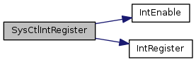
| void SysCtlIntRegister | ( | void(*)(void) | pfnHandler | ) |
Registers an interrupt handler for the system control interrupt.
| pfnHandler | is a pointer to the function to be called when the system control interrupt occurs. |
This function registers the handler to be called when a system control interrupt occurs. This function enables the global interrupt in the interrupt controller; specific system control interrupts must be enabled via SysCtlIntEnable(). It is the interrupt handler's responsibility to clear the interrupt source via SysCtlIntClear().
System control can generate interrupts when the PLL achieves lock, if the internal LDO current limit is exceeded, if the internal oscillator fails, if the main oscillator fails, if the internal LDO output voltage droops too much, if the external voltage droops too much, or if the PLL fails.
Definition at line 1254 of file sysctl.c.
References INT_SYSCTL_TM4C123, IntEnable(), and IntRegister().
| uint32_t SysCtlIntStatus | ( | bool | bMasked | ) |
Gets the current interrupt status.
| bMasked | is false if the raw interrupt status is required and true if the masked interrupt status is required. |
This function returns the interrupt status for the system controller. Either the raw interrupt status or the status of interrupts that are allowed to reflect to the processor can be returned.
Definition at line 1417 of file sysctl.c.
References HWREG, SYSCTL_MISC, and SYSCTL_RIS.
| void SysCtlIntUnregister | ( | void | ) |
Unregisters the interrupt handler for the system control interrupt.
This function unregisters the handler to be called when a system control interrupt occurs. This function also masks off the interrupt in the interrupt controller so that the interrupt handler no longer is called.
Definition at line 1282 of file sysctl.c.
References INT_SYSCTL_TM4C123, IntDisable(), and IntUnregister().

| uint32_t SysCtlLDODeepSleepGet | ( | void | ) |
Returns the output voltage of the LDO when the device enters deep-sleep mode.
This function returns the output voltage of the LDO when the device is in deep-sleep mode, as specified by the control register.
Definition at line 1563 of file sysctl.c.
References HWREG, and SYSCTL_LDODPCTL.
| void SysCtlLDODeepSleepSet | ( | uint32_t | ui32Voltage | ) |
Sets the output voltage of the LDO when the device enters deep-sleep mode.
| ui32Voltage | is the required output voltage from the LDO while in deep-sleep mode. |
This function sets the output voltage of the LDO while in deep-sleep mode. The ui32Voltage parameter specifies the output voltage of the LDO and must be one of the following values: SYSCTL_LDO_0_90V, SYSCTL_LDO_0_95V, SYSCTL_LDO_1_00V, SYSCTL_LDO_1_05V, SYSCTL_LDO_1_10V, SYSCTL_LDO_1_15V, or SYSCTL_LDO_1_20V.
Definition at line 1524 of file sysctl.c.
References ASSERT, HWREG, SYSCTL_LDO_0_90V, SYSCTL_LDO_0_95V, SYSCTL_LDO_1_00V, SYSCTL_LDO_1_05V, SYSCTL_LDO_1_10V, SYSCTL_LDO_1_15V, SYSCTL_LDO_1_20V, and SYSCTL_LDODPCTL.
| uint32_t SysCtlLDOSleepGet | ( | void | ) |
Returns the output voltage of the LDO when the device enters sleep mode.
This function determines the output voltage of the LDO while in sleep mode, as specified by the control register.
Definition at line 1493 of file sysctl.c.
References HWREG, and SYSCTL_LDOSPCTL.
| void SysCtlLDOSleepSet | ( | uint32_t | ui32Voltage | ) |
Sets the output voltage of the LDO when the device enters sleep mode.
| ui32Voltage | is the required output voltage from the LDO while in sleep mode. |
This function sets the output voltage of the LDO while in sleep mode. The ui32Voltage parameter must be one of the following values: SYSCTL_LDO_0_90V, SYSCTL_LDO_0_95V, SYSCTL_LDO_1_00V, SYSCTL_LDO_1_05V, SYSCTL_LDO_1_10V, SYSCTL_LDO_1_15V, or SYSCTL_LDO_1_20V.
Definition at line 1455 of file sysctl.c.
References ASSERT, HWREG, SYSCTL_LDO_0_90V, SYSCTL_LDO_0_95V, SYSCTL_LDO_1_00V, SYSCTL_LDO_1_05V, SYSCTL_LDO_1_10V, SYSCTL_LDO_1_15V, SYSCTL_LDO_1_20V, and SYSCTL_LDOSPCTL.
| void SysCtlMOSCConfigSet | ( | uint32_t | ui32Config | ) |
Provides a small delay.
| ui32Count | is the number of delay loop iterations to perform. |
This function provides a means of generating a delay by executing a simple 3 instruction cycle loop a given number of times. It is written in assembly to keep the loop instruction count consistent across tool chains.
It is important to note that this function does NOT provide an accurate timing mechanism. Although the delay loop is 3 instruction cycles long, the execution time of the loop will vary dramatically depending upon the application's interrupt environment (the loop will be interrupted unless run with interrupts disabled and this is generally an unwise thing to do) and also the current system clock rate and flash timings (wait states and the operation of the prefetch buffer affect the timing).
For better accuracy, the ROM version of this function may be used. This version will not suffer from flash- and prefect buffer-related timing variability but will still be delayed by interrupt service routines.
For best accuracy, a system timer should be used with code either polling for a particular timer value being exceeded or processing the timer interrupt to determine when a particular time period has elapsed.
| ui32Config | is the required configuration of the MOSC control. |
This function configures the control of the main oscillator. The ui32Config is specified as the logical OR of the following values:
Definition at line 1900 of file sysctl.c.
References HWREG, and SYSCTL_MOSCCTL.
| void SysCtlNMIClear | ( | uint32_t | ui32Ints | ) |
Clears NMI sources.
| ui32Ints | is a bit mask of the non-maskable interrupt sources. |
This function clears the current NMI status specified in the ui32Ints parameter. The valid values for the ui32Ints parameter are a logical OR of the following values:
Example: Clear all current NMI status flags.
//!
//! //
//! // Clear all the current NMI sources.
//! //
//! SysCtlNMIClear(SysCtlNMIStatus());
//!
\note The availability of the NMI status varies with the Tiva part in
use.  Please consult the data sheet for the part you are using to determine
which interrupt sources are available.

\return None.
Definition at line 3583 of file sysctl.c.
References HWREG, and SYSCTL_NMIC.
| uint32_t SysCtlNMIStatus | ( | void | ) |
Returns the current NMI status.
This function returns the NMI status for the system controller. The valid values for the ui32Ints parameter are a logical OR of the following values:
Example: Clear all current NMI status flags.
//!
//! //
//! // Clear all the current NMI sources.
//! //
//! SysCtlNMIClear(SysCtlNMIStatus());
//!
\note The availability of the NMI status varies with the Tiva part in
use.  Please consult the data sheet for the part you are using to determine
which interrupt sources are available.

\return The current NMI status.
Definition at line 3543 of file sysctl.c.
References HWREG, and SYSCTL_NMIC.
| void SysCtlPeripheralClockGating | ( | bool | bEnable | ) |
Controls peripheral clock gating in sleep and deep-sleep mode.
| bEnable | is a boolean that is true if the sleep and deep-sleep peripheral configuration should be used and false if not. |
This function controls how peripherals are clocked when the processor goes into sleep or deep-sleep mode. By default, the peripherals are clocked the same as in run mode; if peripheral clock gating is enabled, they are clocked according to the configuration set by SysCtlPeripheralSleepEnable(), SysCtlPeripheralSleepDisable(), SysCtlPeripheralDeepSleepEnable(), and SysCtlPeripheralDeepSleepDisable().
Definition at line 1193 of file sysctl.c.
References CLASS_IS_TM4C123, HWREG, SYSCTL_RCC, SYSCTL_RCC_ACG, SYSCTL_RSCLKCFG, and SYSCTL_RSCLKCFG_ACG.
| void SysCtlPeripheralDeepSleepDisable | ( | uint32_t | ui32Peripheral | ) |
Disables a peripheral in deep-sleep mode.
| ui32Peripheral | is the peripheral to disable in deep-sleep mode. |
This function causes a peripheral to stop operating when the processor goes into deep-sleep mode. Disabling peripherals while in deep-sleep mode helps to lower the current draw of the device, and can keep peripherals that require a particular clock frequency from operating when the clock changes as a result of entering deep-sleep mode. If enabled (via SysCtlPeripheralEnable()), the peripheral automatically resumes operation when the processor leaves deep-sleep mode, maintaining its entire state from before deep-sleep mode was entered.
Deep-sleep mode clocking of peripherals must be enabled via SysCtlPeripheralClockGating(); if disabled, the peripheral deep-sleep mode configuration is maintained but has no effect when deep-sleep mode is entered.
The ui32Peripheral parameter must be only one of the following values: SYSCTL_PERIPH_ADC0, SYSCTL_PERIPH_ADC1, SYSCTL_PERIPH_CAN0, SYSCTL_PERIPH_CAN1, SYSCTL_PERIPH_CCM0,SYSCTL_PERIPH_COMP0, SYSCTL_PERIPH_EEPROM0, SYSCTL_PERIPH_EMAC, SYSCTL_PERIPH_EPHY, SYSCTL_PERIPH_EPI0, SYSCTL_PERIPH_GPIOA, SYSCTL_PERIPH_GPIOB, SYSCTL_PERIPH_GPIOC, SYSCTL_PERIPH_GPIOD, SYSCTL_PERIPH_GPIOE, SYSCTL_PERIPH_GPIOF, SYSCTL_PERIPH_GPIOG, SYSCTL_PERIPH_GPIOH, SYSCTL_PERIPH_GPIOJ, SYSCTL_PERIPH_GPIOK, SYSCTL_PERIPH_GPIOL, SYSCTL_PERIPH_GPIOM, SYSCTL_PERIPH_GPION, SYSCTL_PERIPH_GPIOP, SYSCTL_PERIPH_GPIOQ, SYSCTL_PERIPH_GPIOR, SYSCTL_PERIPH_GPIOS, SYSCTL_PERIPH_GPIOT, SYSCTL_PERIPH_HIBERNATE, SYSCTL_PERIPH_I2C0, SYSCTL_PERIPH_I2C1, SYSCTL_PERIPH_I2C2, SYSCTL_PERIPH_I2C3, SYSCTL_PERIPH_I2C4, SYSCTL_PERIPH_I2C5, SYSCTL_PERIPH_I2C6, SYSCTL_PERIPH_I2C7, SYSCTL_PERIPH_I2C8, SYSCTL_PERIPH_I2C9, SYSCTL_PERIPH_LCD0, SYSCTL_PERIPH_ONEWIRE0, SYSCTL_PERIPH_PWM0, SYSCTL_PERIPH_PWM1, SYSCTL_PERIPH_QEI0, SYSCTL_PERIPH_QEI1, SYSCTL_PERIPH_SSI0, SYSCTL_PERIPH_SSI1, SYSCTL_PERIPH_SSI2, SYSCTL_PERIPH_SSI3, SYSCTL_PERIPH_TIMER0, SYSCTL_PERIPH_TIMER1, SYSCTL_PERIPH_TIMER2, SYSCTL_PERIPH_TIMER3, SYSCTL_PERIPH_TIMER4, SYSCTL_PERIPH_TIMER5, SYSCTL_PERIPH_TIMER6, SYSCTL_PERIPH_TIMER7, SYSCTL_PERIPH_UART0, SYSCTL_PERIPH_UART1, SYSCTL_PERIPH_UART2, SYSCTL_PERIPH_UART3, SYSCTL_PERIPH_UART4, SYSCTL_PERIPH_UART5, SYSCTL_PERIPH_UART6, SYSCTL_PERIPH_UART7, SYSCTL_PERIPH_UDMA, SYSCTL_PERIPH_USB0, SYSCTL_PERIPH_WDOG0, SYSCTL_PERIPH_WDOG1, SYSCTL_PERIPH_WTIMER0, SYSCTL_PERIPH_WTIMER1, SYSCTL_PERIPH_WTIMER2, SYSCTL_PERIPH_WTIMER3, SYSCTL_PERIPH_WTIMER4, or SYSCTL_PERIPH_WTIMER5
Definition at line 1161 of file sysctl.c.
References ASSERT, HWREGBITW, and SYSCTL_DCGCBASE.
| void SysCtlPeripheralDeepSleepEnable | ( | uint32_t | ui32Peripheral | ) |
Enables a peripheral in deep-sleep mode.
| ui32Peripheral | is the peripheral to enable in deep-sleep mode. |
This function allows a peripheral to continue operating when the processor goes into deep-sleep mode. Because the clocking configuration of the device may change, not all peripherals can safely continue operating while the processor is in deep-sleep mode. Those that must run at a particular frequency (such as a UART) do not work as expected if the clock changes. It is the responsibility of the caller to make sensible choices.
Deep-sleep mode clocking of peripherals must be enabled via SysCtlPeripheralClockGating(); if disabled, the peripheral deep-sleep mode configuration is maintained but has no effect when deep-sleep mode is entered.
The ui32Peripheral parameter must be only one of the following values: SYSCTL_PERIPH_ADC0, SYSCTL_PERIPH_ADC1, SYSCTL_PERIPH_CAN0, SYSCTL_PERIPH_CAN1, SYSCTL_PERIPH_CCM0,SYSCTL_PERIPH_COMP0, SYSCTL_PERIPH_EEPROM0, SYSCTL_PERIPH_EMAC, SYSCTL_PERIPH_EPHY, SYSCTL_PERIPH_EPI0, SYSCTL_PERIPH_GPIOA, SYSCTL_PERIPH_GPIOB, SYSCTL_PERIPH_GPIOC, SYSCTL_PERIPH_GPIOD, SYSCTL_PERIPH_GPIOE, SYSCTL_PERIPH_GPIOF, SYSCTL_PERIPH_GPIOG, SYSCTL_PERIPH_GPIOH, SYSCTL_PERIPH_GPIOJ, SYSCTL_PERIPH_GPIOK, SYSCTL_PERIPH_GPIOL, SYSCTL_PERIPH_GPIOM, SYSCTL_PERIPH_GPION, SYSCTL_PERIPH_GPIOP, SYSCTL_PERIPH_GPIOQ, SYSCTL_PERIPH_GPIOR, SYSCTL_PERIPH_GPIOS, SYSCTL_PERIPH_GPIOT, SYSCTL_PERIPH_HIBERNATE, SYSCTL_PERIPH_I2C0, SYSCTL_PERIPH_I2C1, SYSCTL_PERIPH_I2C2, SYSCTL_PERIPH_I2C3, SYSCTL_PERIPH_I2C4, SYSCTL_PERIPH_I2C5, SYSCTL_PERIPH_I2C6, SYSCTL_PERIPH_I2C7, SYSCTL_PERIPH_I2C8, SYSCTL_PERIPH_I2C9, SYSCTL_PERIPH_LCD0, SYSCTL_PERIPH_ONEWIRE0, SYSCTL_PERIPH_PWM0, SYSCTL_PERIPH_PWM1, SYSCTL_PERIPH_QEI0, SYSCTL_PERIPH_QEI1, SYSCTL_PERIPH_SSI0, SYSCTL_PERIPH_SSI1, SYSCTL_PERIPH_SSI2, SYSCTL_PERIPH_SSI3, SYSCTL_PERIPH_TIMER0, SYSCTL_PERIPH_TIMER1, SYSCTL_PERIPH_TIMER2, SYSCTL_PERIPH_TIMER3, SYSCTL_PERIPH_TIMER4, SYSCTL_PERIPH_TIMER5, SYSCTL_PERIPH_TIMER6, SYSCTL_PERIPH_TIMER7, SYSCTL_PERIPH_UART0, SYSCTL_PERIPH_UART1, SYSCTL_PERIPH_UART2, SYSCTL_PERIPH_UART3, SYSCTL_PERIPH_UART4, SYSCTL_PERIPH_UART5, SYSCTL_PERIPH_UART6, SYSCTL_PERIPH_UART7, SYSCTL_PERIPH_UDMA, SYSCTL_PERIPH_USB0, SYSCTL_PERIPH_WDOG0, SYSCTL_PERIPH_WDOG1, SYSCTL_PERIPH_WTIMER0, SYSCTL_PERIPH_WTIMER1, SYSCTL_PERIPH_WTIMER2, SYSCTL_PERIPH_WTIMER3, SYSCTL_PERIPH_WTIMER4, or SYSCTL_PERIPH_WTIMER5
Definition at line 1093 of file sysctl.c.
References ASSERT, HWREGBITW, and SYSCTL_DCGCBASE.
| void SysCtlPeripheralDisable | ( | uint32_t | ui32Peripheral | ) |
Disables a peripheral.
| ui32Peripheral | is the peripheral to disable. |
This function disables a peripheral. Once disabled, they do not operate or respond to register reads/writes.
The ui32Peripheral parameter must be only one of the following values: SYSCTL_PERIPH_ADC0, SYSCTL_PERIPH_ADC1, SYSCTL_PERIPH_CAN0, SYSCTL_PERIPH_CAN1, SYSCTL_PERIPH_CCM0,SYSCTL_PERIPH_COMP0, SYSCTL_PERIPH_EEPROM0, SYSCTL_PERIPH_EMAC, SYSCTL_PERIPH_EPHY, SYSCTL_PERIPH_EPI0, SYSCTL_PERIPH_GPIOA, SYSCTL_PERIPH_GPIOB, SYSCTL_PERIPH_GPIOC, SYSCTL_PERIPH_GPIOD, SYSCTL_PERIPH_GPIOE, SYSCTL_PERIPH_GPIOF, SYSCTL_PERIPH_GPIOG, SYSCTL_PERIPH_GPIOH, SYSCTL_PERIPH_GPIOJ, SYSCTL_PERIPH_GPIOK, SYSCTL_PERIPH_GPIOL, SYSCTL_PERIPH_GPIOM, SYSCTL_PERIPH_GPION, SYSCTL_PERIPH_GPIOP, SYSCTL_PERIPH_GPIOQ, SYSCTL_PERIPH_GPIOR, SYSCTL_PERIPH_GPIOS, SYSCTL_PERIPH_GPIOT, SYSCTL_PERIPH_HIBERNATE, SYSCTL_PERIPH_I2C0, SYSCTL_PERIPH_I2C1, SYSCTL_PERIPH_I2C2, SYSCTL_PERIPH_I2C3, SYSCTL_PERIPH_I2C4, SYSCTL_PERIPH_I2C5, SYSCTL_PERIPH_I2C6, SYSCTL_PERIPH_I2C7, SYSCTL_PERIPH_I2C8, SYSCTL_PERIPH_I2C9, SYSCTL_PERIPH_LCD0, SYSCTL_PERIPH_ONEWIRE0, SYSCTL_PERIPH_PWM0, SYSCTL_PERIPH_PWM1, SYSCTL_PERIPH_QEI0, SYSCTL_PERIPH_QEI1, SYSCTL_PERIPH_SSI0, SYSCTL_PERIPH_SSI1, SYSCTL_PERIPH_SSI2, SYSCTL_PERIPH_SSI3, SYSCTL_PERIPH_TIMER0, SYSCTL_PERIPH_TIMER1, SYSCTL_PERIPH_TIMER2, SYSCTL_PERIPH_TIMER3, SYSCTL_PERIPH_TIMER4, SYSCTL_PERIPH_TIMER5, SYSCTL_PERIPH_TIMER6, SYSCTL_PERIPH_TIMER7, SYSCTL_PERIPH_UART0, SYSCTL_PERIPH_UART1, SYSCTL_PERIPH_UART2, SYSCTL_PERIPH_UART3, SYSCTL_PERIPH_UART4, SYSCTL_PERIPH_UART5, SYSCTL_PERIPH_UART6, SYSCTL_PERIPH_UART7, SYSCTL_PERIPH_UDMA, SYSCTL_PERIPH_USB0, SYSCTL_PERIPH_WDOG0, SYSCTL_PERIPH_WDOG1, SYSCTL_PERIPH_WTIMER0, SYSCTL_PERIPH_WTIMER1, SYSCTL_PERIPH_WTIMER2, SYSCTL_PERIPH_WTIMER3, SYSCTL_PERIPH_WTIMER4, or SYSCTL_PERIPH_WTIMER5
Definition at line 898 of file sysctl.c.
References ASSERT, HWREGBITW, and SYSCTL_RCGCBASE.
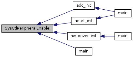
| void SysCtlPeripheralEnable | ( | uint32_t | ui32Peripheral | ) |
Enables a peripheral.
| ui32Peripheral | is the peripheral to enable. |
This function enables a peripheral. At power-up, all peripherals are disabled; they must be enabled in order to operate or respond to register reads/writes.
The ui32Peripheral parameter must be only one of the following values: SYSCTL_PERIPH_ADC0, SYSCTL_PERIPH_ADC1, SYSCTL_PERIPH_CAN0, SYSCTL_PERIPH_CAN1, SYSCTL_PERIPH_CCM0,SYSCTL_PERIPH_COMP0, SYSCTL_PERIPH_EEPROM0, SYSCTL_PERIPH_EMAC, SYSCTL_PERIPH_EPHY, SYSCTL_PERIPH_EPI0, SYSCTL_PERIPH_GPIOA, SYSCTL_PERIPH_GPIOB, SYSCTL_PERIPH_GPIOC, SYSCTL_PERIPH_GPIOD, SYSCTL_PERIPH_GPIOE, SYSCTL_PERIPH_GPIOF, SYSCTL_PERIPH_GPIOG, SYSCTL_PERIPH_GPIOH, SYSCTL_PERIPH_GPIOJ, SYSCTL_PERIPH_GPIOK, SYSCTL_PERIPH_GPIOL, SYSCTL_PERIPH_GPIOM, SYSCTL_PERIPH_GPION, SYSCTL_PERIPH_GPIOP, SYSCTL_PERIPH_GPIOQ, SYSCTL_PERIPH_GPIOR, SYSCTL_PERIPH_GPIOS, SYSCTL_PERIPH_GPIOT, SYSCTL_PERIPH_HIBERNATE, SYSCTL_PERIPH_I2C0, SYSCTL_PERIPH_I2C1, SYSCTL_PERIPH_I2C2, SYSCTL_PERIPH_I2C3, SYSCTL_PERIPH_I2C4, SYSCTL_PERIPH_I2C5, SYSCTL_PERIPH_I2C6, SYSCTL_PERIPH_I2C7, SYSCTL_PERIPH_I2C8, SYSCTL_PERIPH_I2C9, SYSCTL_PERIPH_LCD0, SYSCTL_PERIPH_ONEWIRE0, SYSCTL_PERIPH_PWM0, SYSCTL_PERIPH_PWM1, SYSCTL_PERIPH_QEI0, SYSCTL_PERIPH_QEI1, SYSCTL_PERIPH_SSI0, SYSCTL_PERIPH_SSI1, SYSCTL_PERIPH_SSI2, SYSCTL_PERIPH_SSI3, SYSCTL_PERIPH_TIMER0, SYSCTL_PERIPH_TIMER1, SYSCTL_PERIPH_TIMER2, SYSCTL_PERIPH_TIMER3, SYSCTL_PERIPH_TIMER4, SYSCTL_PERIPH_TIMER5, SYSCTL_PERIPH_TIMER6, SYSCTL_PERIPH_TIMER7, SYSCTL_PERIPH_UART0, SYSCTL_PERIPH_UART1, SYSCTL_PERIPH_UART2, SYSCTL_PERIPH_UART3, SYSCTL_PERIPH_UART4, SYSCTL_PERIPH_UART5, SYSCTL_PERIPH_UART6, SYSCTL_PERIPH_UART7, SYSCTL_PERIPH_UDMA, SYSCTL_PERIPH_USB0, SYSCTL_PERIPH_WDOG0, SYSCTL_PERIPH_WDOG1, SYSCTL_PERIPH_WTIMER0, SYSCTL_PERIPH_WTIMER1, SYSCTL_PERIPH_WTIMER2, SYSCTL_PERIPH_WTIMER3, SYSCTL_PERIPH_WTIMER4, or SYSCTL_PERIPH_WTIMER5
Definition at line 841 of file sysctl.c.
References ASSERT, HWREGBITW, and SYSCTL_RCGCBASE.
Referenced by adc_init(), heart_init(), hw_driver_init(), and main().
| void SysCtlPeripheralPowerOff | ( | uint32_t | ui32Peripheral | ) |
Powers off a peripheral.
| ui32Peripheral | is the peripheral to be powered off. |
This function allows the power to a peripheral to be turned off. The peripheral continues to receive power when its clock is enabled, but the power is removed when its clock is disabled.
The ui32Peripheral parameter must be only one of the following values: SYSCTL_PERIPH_CAN0,SYSCTL_PERIPH_CAN1, SYSCTL_PERIPH_EMAC, SYSCTL_PERIPH_EPHY, SYSCTL_PERIPH_LCD0, SYSCTL_PERIPH_USB0
Definition at line 703 of file sysctl.c.
References ASSERT, HWREGBITW, and SYSCTL_PCBASE.
| void SysCtlPeripheralPowerOn | ( | uint32_t | ui32Peripheral | ) |
Powers on a peripheral.
| ui32Peripheral | is the peripheral to be powered on. |
This function turns on the power to a peripheral. The peripheral continues to receive power even when its clock is not enabled.
The ui32Peripheral parameter must be only one of the following values: SYSCTL_PERIPH_CAN0,SYSCTL_PERIPH_CAN1, SYSCTL_PERIPH_EMAC, SYSCTL_PERIPH_EPHY, SYSCTL_PERIPH_LCD0, SYSCTL_PERIPH_USB0
Definition at line 667 of file sysctl.c.
References ASSERT, HWREGBITW, and SYSCTL_PCBASE.
| bool SysCtlPeripheralPresent | ( | uint32_t | ui32Peripheral | ) |
Determines if a peripheral is present.
| ui32Peripheral | is the peripheral in question. |
This function determines if a particular peripheral is present in the device. Each member of the Tiva family has a different peripheral set; this function determines which peripherals are present on this device.
The ui32Peripheral parameter must be only one of the following values: SYSCTL_PERIPH_ADC0, SYSCTL_PERIPH_ADC1, SYSCTL_PERIPH_CAN0, SYSCTL_PERIPH_CAN1, SYSCTL_PERIPH_CCM0,SYSCTL_PERIPH_COMP0, SYSCTL_PERIPH_EEPROM0, SYSCTL_PERIPH_EMAC, SYSCTL_PERIPH_EPHY, SYSCTL_PERIPH_EPI0, SYSCTL_PERIPH_GPIOA, SYSCTL_PERIPH_GPIOB, SYSCTL_PERIPH_GPIOC, SYSCTL_PERIPH_GPIOD, SYSCTL_PERIPH_GPIOE, SYSCTL_PERIPH_GPIOF, SYSCTL_PERIPH_GPIOG, SYSCTL_PERIPH_GPIOH, SYSCTL_PERIPH_GPIOJ, SYSCTL_PERIPH_GPIOK, SYSCTL_PERIPH_GPIOL, SYSCTL_PERIPH_GPIOM, SYSCTL_PERIPH_GPION, SYSCTL_PERIPH_GPIOP, SYSCTL_PERIPH_GPIOQ, SYSCTL_PERIPH_GPIOR, SYSCTL_PERIPH_GPIOS, SYSCTL_PERIPH_GPIOT, SYSCTL_PERIPH_HIBERNATE, SYSCTL_PERIPH_I2C0, SYSCTL_PERIPH_I2C1, SYSCTL_PERIPH_I2C2, SYSCTL_PERIPH_I2C3, SYSCTL_PERIPH_I2C4, SYSCTL_PERIPH_I2C5, SYSCTL_PERIPH_I2C6, SYSCTL_PERIPH_I2C7, SYSCTL_PERIPH_I2C8, SYSCTL_PERIPH_I2C9, SYSCTL_PERIPH_LCD0, SYSCTL_PERIPH_ONEWIRE0, SYSCTL_PERIPH_PWM0, SYSCTL_PERIPH_PWM1, SYSCTL_PERIPH_QEI0, SYSCTL_PERIPH_QEI1, SYSCTL_PERIPH_SSI0, SYSCTL_PERIPH_SSI1, SYSCTL_PERIPH_SSI2, SYSCTL_PERIPH_SSI3, SYSCTL_PERIPH_TIMER0, SYSCTL_PERIPH_TIMER1, SYSCTL_PERIPH_TIMER2, SYSCTL_PERIPH_TIMER3, SYSCTL_PERIPH_TIMER4, SYSCTL_PERIPH_TIMER5, SYSCTL_PERIPH_TIMER6, SYSCTL_PERIPH_TIMER7, SYSCTL_PERIPH_UART0, SYSCTL_PERIPH_UART1, SYSCTL_PERIPH_UART2, SYSCTL_PERIPH_UART3, SYSCTL_PERIPH_UART4, SYSCTL_PERIPH_UART5, SYSCTL_PERIPH_UART6, SYSCTL_PERIPH_UART7, SYSCTL_PERIPH_UDMA, SYSCTL_PERIPH_USB0, SYSCTL_PERIPH_WDOG0, SYSCTL_PERIPH_WDOG1, SYSCTL_PERIPH_WTIMER0, SYSCTL_PERIPH_WTIMER1, SYSCTL_PERIPH_WTIMER2, SYSCTL_PERIPH_WTIMER3, SYSCTL_PERIPH_WTIMER4, or SYSCTL_PERIPH_WTIMER5
Definition at line 568 of file sysctl.c.
References ASSERT, HWREGBITW, and SYSCTL_PPBASE.
| bool SysCtlPeripheralReady | ( | uint32_t | ui32Peripheral | ) |
Determines if a peripheral is ready.
| ui32Peripheral | is the peripheral in question. |
This function determines if a particular peripheral is ready to be accessed. The peripheral may be in a non-ready state if it is not enabled, is being held in reset, or is in the process of becoming ready after being enabled or taken out of reset.
The ui32Peripheral parameter must be only one of the following values: SYSCTL_PERIPH_ADC0, SYSCTL_PERIPH_ADC1, SYSCTL_PERIPH_CAN0, SYSCTL_PERIPH_CAN1, SYSCTL_PERIPH_CCM0,SYSCTL_PERIPH_COMP0, SYSCTL_PERIPH_EEPROM0, SYSCTL_PERIPH_EMAC, SYSCTL_PERIPH_EPHY, SYSCTL_PERIPH_EPI0, SYSCTL_PERIPH_GPIOA, SYSCTL_PERIPH_GPIOB, SYSCTL_PERIPH_GPIOC, SYSCTL_PERIPH_GPIOD, SYSCTL_PERIPH_GPIOE, SYSCTL_PERIPH_GPIOF, SYSCTL_PERIPH_GPIOG, SYSCTL_PERIPH_GPIOH, SYSCTL_PERIPH_GPIOJ, SYSCTL_PERIPH_GPIOK, SYSCTL_PERIPH_GPIOL, SYSCTL_PERIPH_GPIOM, SYSCTL_PERIPH_GPION, SYSCTL_PERIPH_GPIOP, SYSCTL_PERIPH_GPIOQ, SYSCTL_PERIPH_GPIOR, SYSCTL_PERIPH_GPIOS, SYSCTL_PERIPH_GPIOT, SYSCTL_PERIPH_HIBERNATE, SYSCTL_PERIPH_I2C0, SYSCTL_PERIPH_I2C1, SYSCTL_PERIPH_I2C2, SYSCTL_PERIPH_I2C3, SYSCTL_PERIPH_I2C4, SYSCTL_PERIPH_I2C5, SYSCTL_PERIPH_I2C6, SYSCTL_PERIPH_I2C7, SYSCTL_PERIPH_I2C8, SYSCTL_PERIPH_I2C9, SYSCTL_PERIPH_LCD0, SYSCTL_PERIPH_ONEWIRE0, SYSCTL_PERIPH_PWM0, SYSCTL_PERIPH_PWM1, SYSCTL_PERIPH_QEI0, SYSCTL_PERIPH_QEI1, SYSCTL_PERIPH_SSI0, SYSCTL_PERIPH_SSI1, SYSCTL_PERIPH_SSI2, SYSCTL_PERIPH_SSI3, SYSCTL_PERIPH_TIMER0, SYSCTL_PERIPH_TIMER1, SYSCTL_PERIPH_TIMER2, SYSCTL_PERIPH_TIMER3, SYSCTL_PERIPH_TIMER4, SYSCTL_PERIPH_TIMER5, SYSCTL_PERIPH_TIMER6, SYSCTL_PERIPH_TIMER7, SYSCTL_PERIPH_UART0, SYSCTL_PERIPH_UART1, SYSCTL_PERIPH_UART2, SYSCTL_PERIPH_UART3, SYSCTL_PERIPH_UART4, SYSCTL_PERIPH_UART5, SYSCTL_PERIPH_UART6, SYSCTL_PERIPH_UART7, SYSCTL_PERIPH_UDMA, SYSCTL_PERIPH_USB0, SYSCTL_PERIPH_WDOG0, SYSCTL_PERIPH_WDOG1, SYSCTL_PERIPH_WTIMER0, SYSCTL_PERIPH_WTIMER1, SYSCTL_PERIPH_WTIMER2, SYSCTL_PERIPH_WTIMER3, SYSCTL_PERIPH_WTIMER4, or SYSCTL_PERIPH_WTIMER5
Definition at line 632 of file sysctl.c.
References ASSERT, HWREGBITW, and SYSCTL_PRBASE.
Referenced by EMACPHYConfigSet().

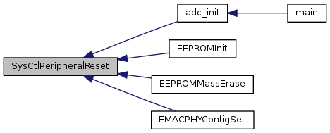
| void SysCtlPeripheralReset | ( | uint32_t | ui32Peripheral | ) |
Performs a software reset of a peripheral.
| ui32Peripheral | is the peripheral to reset. |
This function performs a software reset of the specified peripheral. An individual peripheral reset signal is asserted for a brief period and then de-asserted, returning the internal state of the peripheral to its reset condition.
The ui32Peripheral parameter must be only one of the following values: SYSCTL_PERIPH_ADC0, SYSCTL_PERIPH_ADC1, SYSCTL_PERIPH_CAN0, SYSCTL_PERIPH_CAN1, SYSCTL_PERIPH_CCM0,SYSCTL_PERIPH_COMP0, SYSCTL_PERIPH_EEPROM0, SYSCTL_PERIPH_EMAC, SYSCTL_PERIPH_EPHY, SYSCTL_PERIPH_EPI0, SYSCTL_PERIPH_GPIOA, SYSCTL_PERIPH_GPIOB, SYSCTL_PERIPH_GPIOC, SYSCTL_PERIPH_GPIOD, SYSCTL_PERIPH_GPIOE, SYSCTL_PERIPH_GPIOF, SYSCTL_PERIPH_GPIOG, SYSCTL_PERIPH_GPIOH, SYSCTL_PERIPH_GPIOJ, SYSCTL_PERIPH_GPIOK, SYSCTL_PERIPH_GPIOL, SYSCTL_PERIPH_GPIOM, SYSCTL_PERIPH_GPION, SYSCTL_PERIPH_GPIOP, SYSCTL_PERIPH_GPIOQ, SYSCTL_PERIPH_GPIOR, SYSCTL_PERIPH_GPIOS, SYSCTL_PERIPH_GPIOT, SYSCTL_PERIPH_HIBERNATE, SYSCTL_PERIPH_I2C0, SYSCTL_PERIPH_I2C1, SYSCTL_PERIPH_I2C2, SYSCTL_PERIPH_I2C3, SYSCTL_PERIPH_I2C4, SYSCTL_PERIPH_I2C5, SYSCTL_PERIPH_I2C6, SYSCTL_PERIPH_I2C7, SYSCTL_PERIPH_I2C8, SYSCTL_PERIPH_I2C9, SYSCTL_PERIPH_LCD0, SYSCTL_PERIPH_ONEWIRE0, SYSCTL_PERIPH_PWM0, SYSCTL_PERIPH_PWM1, SYSCTL_PERIPH_QEI0, SYSCTL_PERIPH_QEI1, SYSCTL_PERIPH_SSI0, SYSCTL_PERIPH_SSI1, SYSCTL_PERIPH_SSI2, SYSCTL_PERIPH_SSI3, SYSCTL_PERIPH_TIMER0, SYSCTL_PERIPH_TIMER1, SYSCTL_PERIPH_TIMER2, SYSCTL_PERIPH_TIMER3, SYSCTL_PERIPH_TIMER4, SYSCTL_PERIPH_TIMER5, SYSCTL_PERIPH_TIMER6, SYSCTL_PERIPH_TIMER7, SYSCTL_PERIPH_UART0, SYSCTL_PERIPH_UART1, SYSCTL_PERIPH_UART2, SYSCTL_PERIPH_UART3, SYSCTL_PERIPH_UART4, SYSCTL_PERIPH_UART5, SYSCTL_PERIPH_UART6, SYSCTL_PERIPH_UART7, SYSCTL_PERIPH_UDMA, SYSCTL_PERIPH_USB0, SYSCTL_PERIPH_WDOG0, SYSCTL_PERIPH_WDOG1, SYSCTL_PERIPH_WTIMER0, SYSCTL_PERIPH_WTIMER1, SYSCTL_PERIPH_WTIMER2, SYSCTL_PERIPH_WTIMER3, SYSCTL_PERIPH_WTIMER4, or SYSCTL_PERIPH_WTIMER5
Definition at line 762 of file sysctl.c.
References ASSERT, HWREGBITW, and SYSCTL_SRBASE.
Referenced by adc_init(), EEPROMInit(), EEPROMMassErase(), and EMACPHYConfigSet().
| void SysCtlPeripheralSleepDisable | ( | uint32_t | ui32Peripheral | ) |
Disables a peripheral in sleep mode.
| ui32Peripheral | is the peripheral to disable in sleep mode. |
This function causes a peripheral to stop operating when the processor goes into sleep mode. Disabling peripherals while in sleep mode helps to lower the current draw of the device. If enabled (via SysCtlPeripheralEnable()), the peripheral automatically resumes operation when the processor leaves sleep mode, maintaining its entire state from before sleep mode was entered.
Sleep mode clocking of peripherals must be enabled via SysCtlPeripheralClockGating(); if disabled, the peripheral sleep mode configuration is maintained but has no effect when sleep mode is entered.
The ui32Peripheral parameter must be only one of the following values: SYSCTL_PERIPH_ADC0, SYSCTL_PERIPH_ADC1, SYSCTL_PERIPH_CAN0, SYSCTL_PERIPH_CAN1, SYSCTL_PERIPH_CCM0,SYSCTL_PERIPH_COMP0, SYSCTL_PERIPH_EEPROM0, SYSCTL_PERIPH_EMAC, SYSCTL_PERIPH_EPHY, SYSCTL_PERIPH_EPI0, SYSCTL_PERIPH_GPIOA, SYSCTL_PERIPH_GPIOB, SYSCTL_PERIPH_GPIOC, SYSCTL_PERIPH_GPIOD, SYSCTL_PERIPH_GPIOE, SYSCTL_PERIPH_GPIOF, SYSCTL_PERIPH_GPIOG, SYSCTL_PERIPH_GPIOH, SYSCTL_PERIPH_GPIOJ, SYSCTL_PERIPH_GPIOK, SYSCTL_PERIPH_GPIOL, SYSCTL_PERIPH_GPIOM, SYSCTL_PERIPH_GPION, SYSCTL_PERIPH_GPIOP, SYSCTL_PERIPH_GPIOQ, SYSCTL_PERIPH_GPIOR, SYSCTL_PERIPH_GPIOS, SYSCTL_PERIPH_GPIOT, SYSCTL_PERIPH_HIBERNATE, SYSCTL_PERIPH_I2C0, SYSCTL_PERIPH_I2C1, SYSCTL_PERIPH_I2C2, SYSCTL_PERIPH_I2C3, SYSCTL_PERIPH_I2C4, SYSCTL_PERIPH_I2C5, SYSCTL_PERIPH_I2C6, SYSCTL_PERIPH_I2C7, SYSCTL_PERIPH_I2C8, SYSCTL_PERIPH_I2C9, SYSCTL_PERIPH_LCD0, SYSCTL_PERIPH_ONEWIRE0, SYSCTL_PERIPH_PWM0, SYSCTL_PERIPH_PWM1, SYSCTL_PERIPH_QEI0, SYSCTL_PERIPH_QEI1, SYSCTL_PERIPH_SSI0, SYSCTL_PERIPH_SSI1, SYSCTL_PERIPH_SSI2, SYSCTL_PERIPH_SSI3, SYSCTL_PERIPH_TIMER0, SYSCTL_PERIPH_TIMER1, SYSCTL_PERIPH_TIMER2, SYSCTL_PERIPH_TIMER3, SYSCTL_PERIPH_TIMER4, SYSCTL_PERIPH_TIMER5, SYSCTL_PERIPH_TIMER6, SYSCTL_PERIPH_TIMER7, SYSCTL_PERIPH_UART0, SYSCTL_PERIPH_UART1, SYSCTL_PERIPH_UART2, SYSCTL_PERIPH_UART3, SYSCTL_PERIPH_UART4, SYSCTL_PERIPH_UART5, SYSCTL_PERIPH_UART6, SYSCTL_PERIPH_UART7, SYSCTL_PERIPH_UDMA, SYSCTL_PERIPH_USB0, SYSCTL_PERIPH_WDOG0, SYSCTL_PERIPH_WDOG1, SYSCTL_PERIPH_WTIMER0, SYSCTL_PERIPH_WTIMER1, SYSCTL_PERIPH_WTIMER2, SYSCTL_PERIPH_WTIMER3, SYSCTL_PERIPH_WTIMER4, or SYSCTL_PERIPH_WTIMER5
Definition at line 1027 of file sysctl.c.
References ASSERT, HWREGBITW, and SYSCTL_SCGCBASE.
| void SysCtlPeripheralSleepEnable | ( | uint32_t | ui32Peripheral | ) |
Enables a peripheral in sleep mode.
| ui32Peripheral | is the peripheral to enable in sleep mode. |
This function allows a peripheral to continue operating when the processor goes into sleep mode. Because the clocking configuration of the device does not change, any peripheral can safely continue operating while the processor is in sleep mode and can therefore wake the processor from sleep mode.
Sleep mode clocking of peripherals must be enabled via SysCtlPeripheralClockGating(); if disabled, the peripheral sleep mode configuration is maintained but has no effect when sleep mode is entered.
The ui32Peripheral parameter must be only one of the following values: SYSCTL_PERIPH_ADC0, SYSCTL_PERIPH_ADC1, SYSCTL_PERIPH_CAN0, SYSCTL_PERIPH_CAN1, SYSCTL_PERIPH_CCM0,SYSCTL_PERIPH_COMP0, SYSCTL_PERIPH_EEPROM0, SYSCTL_PERIPH_EMAC, SYSCTL_PERIPH_EPHY, SYSCTL_PERIPH_EPI0, SYSCTL_PERIPH_GPIOA, SYSCTL_PERIPH_GPIOB, SYSCTL_PERIPH_GPIOC, SYSCTL_PERIPH_GPIOD, SYSCTL_PERIPH_GPIOE, SYSCTL_PERIPH_GPIOF, SYSCTL_PERIPH_GPIOG, SYSCTL_PERIPH_GPIOH, SYSCTL_PERIPH_GPIOJ, SYSCTL_PERIPH_GPIOK, SYSCTL_PERIPH_GPIOL, SYSCTL_PERIPH_GPIOM, SYSCTL_PERIPH_GPION, SYSCTL_PERIPH_GPIOP, SYSCTL_PERIPH_GPIOQ, SYSCTL_PERIPH_GPIOR, SYSCTL_PERIPH_GPIOS, SYSCTL_PERIPH_GPIOT, SYSCTL_PERIPH_HIBERNATE, SYSCTL_PERIPH_I2C0, SYSCTL_PERIPH_I2C1, SYSCTL_PERIPH_I2C2, SYSCTL_PERIPH_I2C3, SYSCTL_PERIPH_I2C4, SYSCTL_PERIPH_I2C5, SYSCTL_PERIPH_I2C6, SYSCTL_PERIPH_I2C7, SYSCTL_PERIPH_I2C8, SYSCTL_PERIPH_I2C9, SYSCTL_PERIPH_LCD0, SYSCTL_PERIPH_ONEWIRE0, SYSCTL_PERIPH_PWM0, SYSCTL_PERIPH_PWM1, SYSCTL_PERIPH_QEI0, SYSCTL_PERIPH_QEI1, SYSCTL_PERIPH_SSI0, SYSCTL_PERIPH_SSI1, SYSCTL_PERIPH_SSI2, SYSCTL_PERIPH_SSI3, SYSCTL_PERIPH_TIMER0, SYSCTL_PERIPH_TIMER1, SYSCTL_PERIPH_TIMER2, SYSCTL_PERIPH_TIMER3, SYSCTL_PERIPH_TIMER4, SYSCTL_PERIPH_TIMER5, SYSCTL_PERIPH_TIMER6, SYSCTL_PERIPH_TIMER7, SYSCTL_PERIPH_UART0, SYSCTL_PERIPH_UART1, SYSCTL_PERIPH_UART2, SYSCTL_PERIPH_UART3, SYSCTL_PERIPH_UART4, SYSCTL_PERIPH_UART5, SYSCTL_PERIPH_UART6, SYSCTL_PERIPH_UART7, SYSCTL_PERIPH_UDMA, SYSCTL_PERIPH_USB0, SYSCTL_PERIPH_WDOG0, SYSCTL_PERIPH_WDOG1, SYSCTL_PERIPH_WTIMER0, SYSCTL_PERIPH_WTIMER1, SYSCTL_PERIPH_WTIMER2, SYSCTL_PERIPH_WTIMER3, SYSCTL_PERIPH_WTIMER4, or SYSCTL_PERIPH_WTIMER5
Definition at line 962 of file sysctl.c.
References ASSERT, HWREGBITW, and SYSCTL_SCGCBASE.
| uint32_t SysCtlPIOSCCalibrate | ( | uint32_t | ui32Type | ) |
Calibrates the precision internal oscillator.
| ui32Type | is the type of calibration to perform. |
This function performs a calibration of the PIOSC. There are three types of calibration available; the desired calibration type as specified in ui32Type is one of:
Definition at line 1937 of file sysctl.c.
References HWREG, SYSCTL_PIOSCCAL, SYSCTL_PIOSCCAL_CAL, SYSCTL_PIOSCCAL_UPDATE, SYSCTL_PIOSCCAL_UT_M, SYSCTL_PIOSCCAL_UTEN, SYSCTL_PIOSCSTAT, SYSCTL_PIOSCSTAT_CR_M, and SYSCTL_PIOSCSTAT_CRPASS.
| uint32_t SysCtlPWMClockGet | ( | void | ) |
Gets the current PWM clock configuration.
This function returns the current PWM clock configuration.
Definition at line 3195 of file sysctl.c.
References ASSERT, HWREG, SYSCTL_DC1, SYSCTL_DC1_PWM0, SYSCTL_DC1_PWM1, SYSCTL_PWMDIV_1, SYSCTL_RCC, SYSCTL_RCC_PWMDIV_M, and SYSCTL_RCC_USEPWMDIV.
| void SysCtlPWMClockSet | ( | uint32_t | ui32Config | ) |
Sets the PWM clock configuration.
| ui32Config | is the configuration for the PWM clock; it must be one of SYSCTL_PWMDIV_1, SYSCTL_PWMDIV_2, SYSCTL_PWMDIV_4, SYSCTL_PWMDIV_8, SYSCTL_PWMDIV_16, SYSCTL_PWMDIV_32, or SYSCTL_PWMDIV_64. |
This function configures the rate of the clock provided to the PWM module as a ratio of the processor clock. This clock is used by the PWM module to generate PWM signals; its rate forms the basis for all PWM signals.
Definition at line 3152 of file sysctl.c.
References ASSERT, HWREG, SYSCTL_DC1, SYSCTL_DC1_PWM0, SYSCTL_DC1_PWM1, SYSCTL_PWMDIV_1, SYSCTL_PWMDIV_16, SYSCTL_PWMDIV_2, SYSCTL_PWMDIV_32, SYSCTL_PWMDIV_4, SYSCTL_PWMDIV_64, SYSCTL_PWMDIV_8, SYSCTL_RCC, SYSCTL_RCC_PWMDIV_M, and SYSCTL_RCC_USEPWMDIV.
| void SysCtlReset | ( | void | ) |
Resets the device.
This function performs a software reset of the entire device. The processor and all peripherals are reset and all device registers are returned to their default values (with the exception of the reset cause register, which maintains its current value but has the software reset bit set as well).
Definition at line 1671 of file sysctl.c.
References HWREG, NVIC_APINT, NVIC_APINT_SYSRESETREQ, and NVIC_APINT_VECTKEY.
| uint32_t SysCtlResetBehaviorGet | ( | void | ) |
Returns the current types of reset issued due to reset events.
This function returns the types of resets issued when a configurable reset occurs. The value returned is a logical OR combination of the valid values that are described in the documentation for the ui32Behavior parameter of the SysCtlResetBehaviorSet() function.
Definition at line 2051 of file sysctl.c.
References HWREG, and SYSCTL_RESBEHAVCTL.
| void SysCtlResetBehaviorSet | ( | uint32_t | ui32Behavior | ) |
Sets the type of reset issued due to certain reset events.
| ui32Behavior | specifies the types of resets for each of the configurable reset events. |
This function sets the types of reset issued when a configurable reset event occurs. The reset events that are configurable are: Watchdog 0 or 1, a brown out and the external RSTn pin. The valid actions are either a system reset or a full POR sequence. See the data sheet for more information on the differences between a full POR and a system reset. All reset behaviors can be configured with a single call using the logical OR of the values defined below. Any reset option that is not specifically set remains configured for its default behavior. Either POR or system reset can be selected for each reset cause.
Valid values are logical combinations of the following:
Example: Set Watchdog 0 reset to trigger a POR and a brown-out reset to trigger a system reset while leaving the remaining resets with their default behaviors.
//! SysCtlResetBehaviorSet(SYSCTL_ONRST_WDOG0_POR | SYSCTL_ONRST_BOR_SYS);
//!
\note This function cannot be used with TM4C123 devices.

\return None.
Definition at line 2031 of file sysctl.c.
References HWREG, and SYSCTL_RESBEHAVCTL.
| void SysCtlResetCauseClear | ( | uint32_t | ui32Causes | ) |
Clears reset reasons.
| ui32Causes | are the reset causes to be cleared; must be a logical OR of SYSCTL_CAUSE_HSRVREQ, SYSCTL_CAUSE_HIB, SYSCTL_CAUSE_WDOG1, SYSCTL_CAUSE_SW, SYSCTL_CAUSE_WDOG0, SYSCTL_CAUSE_BOR, SYSCTL_CAUSE_POR, and/or SYSCTL_CAUSE_EXT. |
This function clears the specified sticky reset reasons. Once cleared, another reset for the same reason can be detected, and a reset for a different reason can be distinguished (instead of having two reset causes set). If the reset reason is used by an application, all reset causes should be cleared after they are retrieved with SysCtlResetCauseGet().
Definition at line 1787 of file sysctl.c.
References HWREG, and SYSCTL_RESC.
| uint32_t SysCtlResetCauseGet | ( | void | ) |
Gets the reason for a reset.
This function returns the reason(s) for a reset. Because the reset reasons are sticky until either cleared by software or a power-on reset, multiple reset reasons may be returned if multiple resets have occurred. The reset reason is a logical OR of SYSCTL_CAUSE_HSRVREQ, SYSCTL_CAUSE_HIB, SYSCTL_CAUSE_WDOG1, SYSCTL_CAUSE_SW, SYSCTL_CAUSE_WDOG0, SYSCTL_CAUSE_BOR, SYSCTL_CAUSE_POR, and/or SYSCTL_CAUSE_EXT.
Definition at line 1760 of file sysctl.c.
References HWREG, and SYSCTL_RESC.
| void SysCtlSleep | ( | void | ) |
Puts the processor into sleep mode.
This function places the processor into sleep mode; it does not return until the processor returns to run mode. The peripherals that are enabled via SysCtlPeripheralSleepEnable() continue to operate and can wake up the processor (if automatic clock gating is enabled with SysCtlPeripheralClockGating(), otherwise all peripherals continue to operate).
Definition at line 1703 of file sysctl.c.
References CPUwfi().

| void SysCtlSleepPowerSet | ( | uint32_t | ui32Config | ) |
Configures the power to the flash and SRAM while in sleep mode.
| ui32Config | is the required flash and SRAM power configuration. |
This function allows the power configuration of the flash and SRAM while in sleep mode to be set. The ui32Config parameter is the logical OR of the flash power configuration and the SRAM power configuration.
The flash power configuration is specified as either:
The SRAM power configuration is specified as one of:
Definition at line 1605 of file sysctl.c.
References HWREG, and SYSCTL_SLPPWRCFG.
| uint32_t SysCtlSRAMSizeGet | ( | void | ) |
Gets the size of the SRAM.
This function determines the size of the SRAM on the Tiva device.
Definition at line 452 of file sysctl.c.
References FLASH_SSIZE, and HWREG.
| void SysCtlUSBPLLDisable | ( | void | ) |
Powers down the USB PLL.
This function disables the USB controller's PLL, which is used by its physical layer. The USB registers are still accessible, but the physical layer no longer functions.
Definition at line 3351 of file sysctl.c.
References HWREG, SYSCTL_RCC2, and SYSCTL_RCC2_USBPWRDN.
| void SysCtlUSBPLLEnable | ( | void | ) |
Powers up the USB PLL.
This function enables the USB controller's PLL, which is used by its physical layer. This call is necessary before connecting to any external devices.
Definition at line 3329 of file sysctl.c.
References HWREG, SYSCTL_RCC2, and SYSCTL_RCC2_USBPWRDN.
| void SysCtlVoltageEventClear | ( | uint32_t | ui32Status | ) |
Clears the voltage event status.
| ui32Status | is a bit mask of the voltage events to clear. |
This function clears the current voltage events status for the values specified in the ui32Status parameter. The ui32Status value must be a logical OR of the following values:
Example: Clear the current voltage event status.
//! //
//! // Clear all the current voltage events.
//! //
//! SysCtlVoltageEventClear(SysCtlVoltageEventStatus());
//!
\note The availability of voltage event status varies with the
Tiva part in use.  Please consult the data sheet for the part you are
using to determine which interrupt sources are available.

\return None.
Definition at line 3502 of file sysctl.c.
References HWREG, and SYSCTL_PWRTC.
| void SysCtlVoltageEventConfig | ( | uint32_t | ui32Config | ) |
Configures the response to system voltage events.
| ui32Config | holds the configuration options for the voltage events. |
This function configures the response to voltage-related events. These events are triggered when the voltage rails drop below certain levels. The ui32Config parameter provides the configuration for the voltage events and is a combination of the SYSCTL_VEVENT_* values.
The response to a brown out on the VDDA rail is set by using one of the following values:
The response to a brown out on the VDD rail is set by using one of the following values:
Example: Configure the voltage events to trigger an interrupt on a VDDA brown out, an NMI on a VDDC brown out and a reset on a VDD brown out.
//!
//! //
//! // Configure the BOR rest to trigger a full POR.  This is needed because
//! // the SysCtlVoltageEventConfig() call is triggering a reset so the type
//! // of reset is specified by this call.
//! //
//! SysCtlResetBehaviorSet(SYSCTL_ONRST_BOR_POR);
//!
//! //
//! // Trigger an interrupt on a VDDA brown out and a reset on a VDD brown out.
//! //
//! SysCtlVoltageEventConfig(SYSCTL_VEVENT_VDDABO_INT |
//!                          SYSCTL_VEVENT_VDDBO_RST);
//!
\return None.
Definition at line 3419 of file sysctl.c.
References HWREG, and SYSCTL_PTBOCTL.
| uint32_t SysCtlVoltageEventStatus | ( | void | ) |
Returns the voltage event status.
This function returns the voltage event status for the system controller. The value returned is a logical OR of the following values:
The values returned from this function can be passed to the SysCtlVoltageEventClear() to clear the current voltage event status. Because voltage events are not cleared due to a reset, the voltage event status must be cleared by calling SysCtlVoltageEventClear().
Example: Clear the current voltage event status.
//! uint32_t ui32VoltageEvents;
//!
//! //
//! // Read the current voltage event status.
//! //
//! ui32VoltageEvents = SysCtlVoltageEventStatus();
//!
//! //
//! // Clear all the current voltage events.
//! //
//! SysCtlVoltageEventClear(ui32VoltageEvents);
//!
\return The current voltage event status.

\note The availability of voltage events varies with the Tiva part
in use.  Please consult the data sheet for the part you are using to
determine which interrupt sources are available.
Definition at line 3465 of file sysctl.c.
References HWREG, and SYSCTL_PWRTC.
|
static |
Definition at line 137 of file sysctl.c.
Referenced by SysCtlClockFreqSet().
|
static |
|
static |
Definition at line 81 of file sysctl.c.
Referenced by SysCtlClockFreqSet(), and SysCtlClockGet().
| const { ... } g_sXTALtoMEMTIM[] |
Referenced by _SysCtlMemTimingGet().
 1.8.9.1
