EE445M RTOS
Taken at the University of Texas Spring 2015
Pwm_api

Macros

#define PWM_GEN_BADDR(_mod_, _gen_)   ((_mod_) + (_gen_))
 
#define PWM_GEN_EXT_BADDR(_mod_, _gen_)
 
#define PWM_OUT_BADDR(_mod_, _out_)   ((_mod_) + ((_out_) & 0xFFFFFFC0))
 
#define PWM_IS_OUTPUT_ODD(_out_)   ((_out_) & 0x00000001)
 

Functions

void PWMGenConfigure (uint32_t ui32Base, uint32_t ui32Gen, uint32_t ui32Config)
 
void PWMGenPeriodSet (uint32_t ui32Base, uint32_t ui32Gen, uint32_t ui32Period)
 
uint32_t PWMGenPeriodGet (uint32_t ui32Base, uint32_t ui32Gen)
 
void PWMGenEnable (uint32_t ui32Base, uint32_t ui32Gen)
 
void PWMGenDisable (uint32_t ui32Base, uint32_t ui32Gen)
 
void PWMPulseWidthSet (uint32_t ui32Base, uint32_t ui32PWMOut, uint32_t ui32Width)
 
uint32_t PWMPulseWidthGet (uint32_t ui32Base, uint32_t ui32PWMOut)
 
void PWMDeadBandEnable (uint32_t ui32Base, uint32_t ui32Gen, uint16_t ui16Rise, uint16_t ui16Fall)
 
void PWMDeadBandDisable (uint32_t ui32Base, uint32_t ui32Gen)
 
void PWMSyncUpdate (uint32_t ui32Base, uint32_t ui32GenBits)
 
void PWMSyncTimeBase (uint32_t ui32Base, uint32_t ui32GenBits)
 
void PWMOutputState (uint32_t ui32Base, uint32_t ui32PWMOutBits, bool bEnable)
 
void PWMOutputInvert (uint32_t ui32Base, uint32_t ui32PWMOutBits, bool bInvert)
 
void PWMOutputFaultLevel (uint32_t ui32Base, uint32_t ui32PWMOutBits, bool bDriveHigh)
 
void PWMOutputFault (uint32_t ui32Base, uint32_t ui32PWMOutBits, bool bFaultSuppress)
 
static uint32_t _PWMGenIntNumberGet (uint32_t ui32Base, uint32_t ui32Gen)
 
void PWMGenIntRegister (uint32_t ui32Base, uint32_t ui32Gen, void(*pfnIntHandler)(void))
 
void PWMGenIntUnregister (uint32_t ui32Base, uint32_t ui32Gen)
 
static uint32_t _PWMFaultIntNumberGet (uint32_t ui32Base)
 
void PWMFaultIntRegister (uint32_t ui32Base, void(*pfnIntHandler)(void))
 
void PWMFaultIntUnregister (uint32_t ui32Base)
 
void PWMGenIntTrigEnable (uint32_t ui32Base, uint32_t ui32Gen, uint32_t ui32IntTrig)
 
void PWMGenIntTrigDisable (uint32_t ui32Base, uint32_t ui32Gen, uint32_t ui32IntTrig)
 
uint32_t PWMGenIntStatus (uint32_t ui32Base, uint32_t ui32Gen, bool bMasked)
 
void PWMGenIntClear (uint32_t ui32Base, uint32_t ui32Gen, uint32_t ui32Ints)
 
void PWMIntEnable (uint32_t ui32Base, uint32_t ui32GenFault)
 
void PWMIntDisable (uint32_t ui32Base, uint32_t ui32GenFault)
 
void PWMFaultIntClear (uint32_t ui32Base)
 
uint32_t PWMIntStatus (uint32_t ui32Base, bool bMasked)
 
void PWMFaultIntClearExt (uint32_t ui32Base, uint32_t ui32FaultInts)
 
void PWMGenFaultConfigure (uint32_t ui32Base, uint32_t ui32Gen, uint32_t ui32MinFaultPeriod, uint32_t ui32FaultSenses)
 
void PWMGenFaultTriggerSet (uint32_t ui32Base, uint32_t ui32Gen, uint32_t ui32Group, uint32_t ui32FaultTriggers)
 
uint32_t PWMGenFaultTriggerGet (uint32_t ui32Base, uint32_t ui32Gen, uint32_t ui32Group)
 
uint32_t PWMGenFaultStatus (uint32_t ui32Base, uint32_t ui32Gen, uint32_t ui32Group)
 
void PWMGenFaultClear (uint32_t ui32Base, uint32_t ui32Gen, uint32_t ui32Group, uint32_t ui32FaultTriggers)
 
void PWMClockSet (uint32_t ui32Base, uint32_t ui32Config)
 
uint32_t PWMClockGet (uint32_t ui32Base)
 
void PWMOutputUpdateMode (uint32_t ui32Base, uint32_t ui32PWMOutBits, uint32_t ui32Mode)
 

Detailed Description

Macro Definition Documentation

#define PWM_GEN_EXT_BADDR (   _mod_,
  _gen_ 
)
Value:
((_mod_) + PWM_GEN_EXT_0 + \
((_gen_) - PWM_GEN_0) * 2)
#define PWM_GEN_0
Definition: pwm.h:134
#define PWM_GEN_EXT_0
Definition: pwm.h:144

Definition at line 66 of file pwm.c.

Referenced by PWMGenFaultClear(), PWMGenFaultConfigure(), and PWMGenFaultStatus().

#define PWM_IS_OUTPUT_ODD (   _out_)    ((_out_) & 0x00000001)

Definition at line 71 of file pwm.c.

Referenced by PWMPulseWidthGet(), and PWMPulseWidthSet().

#define PWM_OUT_BADDR (   _mod_,
  _out_ 
)    ((_mod_) + ((_out_) & 0xFFFFFFC0))

Definition at line 69 of file pwm.c.

Referenced by PWMPulseWidthGet(), and PWMPulseWidthSet().

Function Documentation

static uint32_t _PWMFaultIntNumberGet ( uint32_t  ui32Base)
static

Gets the PWM fault interrupt number.

Parameters
ui32Baseis the base address of the PWM module.

This function returns the fault interrupt number of the corresponding PWM module.

Returns
Returns the interrupt number.

Definition at line 1179 of file pwm.c.

References CLASS_IS_TM4C123, CLASS_IS_TM4C129, INT_PWM0_FAULT_TM4C123, INT_PWM0_FAULT_TM4C129, INT_PWM1_FAULT_TM4C123, and PWM0_BASE.

Referenced by PWMFaultIntRegister(), and PWMFaultIntUnregister().

1180 {
1181  //
1182  // Return the fault interrupt number.
1183  //
1184  if(CLASS_IS_TM4C123)
1185  {
1186  return((ui32Base == PWM0_BASE) ? INT_PWM0_FAULT_TM4C123 :
1188  }
1189  else if(CLASS_IS_TM4C129)
1190  {
1191  return((ui32Base == PWM0_BASE) ? INT_PWM0_FAULT_TM4C129 : 0);
1192  }
1193  else
1194  {
1195  return(0);
1196  }
1197 }
#define INT_PWM0_FAULT_TM4C123
Definition: hw_ints.h:73
#define INT_PWM1_FAULT_TM4C123
Definition: hw_ints.h:168
#define CLASS_IS_TM4C123
Definition: hw_types.h:93
#define INT_PWM0_FAULT_TM4C129
Definition: hw_ints.h:185
#define PWM0_BASE
Definition: hw_memmap.h:77
#define CLASS_IS_TM4C129
Definition: hw_types.h:99

Here is the caller graph for this function:

static uint32_t _PWMGenIntNumberGet ( uint32_t  ui32Base,
uint32_t  ui32Gen 
)
static

Gets the PWM generator interrupt number.

Parameters
ui32Baseis the base address of the PWM module.
ui32Genis the PWM generator in question. This parameter must be one of PWM_GEN_0, PWM_GEN_1, PWM_GEN_2, or PWM_GEN_3.

This function returns the interrupt number of the corresponding PWM generator.

Returns
Returns the interrupt number.

Definition at line 923 of file pwm.c.

References CLASS_IS_TM4C123, CLASS_IS_TM4C129, INT_PWM0_0_TM4C123, INT_PWM0_0_TM4C129, INT_PWM0_1_TM4C129, INT_PWM0_2_TM4C129, INT_PWM0_3_TM4C129, INT_PWM1_0_TM4C123, INT_PWM1_1_TM4C123, INT_PWM1_2_TM4C123, INT_PWM1_3_TM4C123, PWM0_BASE, PWM1_BASE, PWM_GEN_0, PWM_GEN_1, PWM_GEN_2, and PWM_GEN_3.

Referenced by PWMGenIntRegister(), and PWMGenIntUnregister().

924 {
925  //
926  // Determine the generator and PWM module in question.
927  //
928  switch(ui32Base + ui32Gen)
929  {
930  //
931  // The first PWM generator in the first PWM module.
932  //
933  case PWM0_BASE + PWM_GEN_0:
934  {
935  if(CLASS_IS_TM4C123)
936  {
937  return(INT_PWM0_0_TM4C123);
938  }
939  else if(CLASS_IS_TM4C129)
940  {
941  return(INT_PWM0_0_TM4C129);
942  }
943  else
944  {
945  return(0);
946  }
947  }
948 
949  //
950  // The second PWM generator in the first PWM module.
951  //
952  case PWM0_BASE + PWM_GEN_1:
953  {
954  if(CLASS_IS_TM4C129)
955  {
956  return(INT_PWM0_1_TM4C129);
957  }
958  else
959  {
960  return(0);
961  }
962  }
963 
964  //
965  // The third PWM generator in the first PWM module.
966  //
967  case PWM0_BASE + PWM_GEN_2:
968  {
969  if(CLASS_IS_TM4C129)
970  {
971  return(INT_PWM0_2_TM4C129);
972  }
973  else
974  {
975  return(0);
976  }
977  }
978 
979  //
980  // The fourth PWM generator in the first PWM module.
981  //
982  case PWM0_BASE + PWM_GEN_3:
983  {
984  if(CLASS_IS_TM4C129)
985  {
986  return(INT_PWM0_3_TM4C129);
987  }
988  else
989  {
990  return(0);
991  }
992  }
993 
994  //
995  // The first PWM generator in the second PWM module.
996  //
997  case PWM1_BASE + PWM_GEN_0:
998  {
999  if(CLASS_IS_TM4C123)
1000  {
1001  return(INT_PWM1_0_TM4C123);
1002  }
1003  else
1004  {
1005  return(0);
1006  }
1007  }
1008 
1009  //
1010  // The first PWM generator in the second PWM module.
1011  //
1012  case PWM1_BASE + PWM_GEN_1:
1013  {
1014  if(CLASS_IS_TM4C123)
1015  {
1016  return(INT_PWM1_1_TM4C123);
1017  }
1018  else
1019  {
1020  return(0);
1021  }
1022  }
1023 
1024  //
1025  // The first PWM generator in the second PWM module.
1026  //
1027  case PWM1_BASE + PWM_GEN_2:
1028  {
1029  if(CLASS_IS_TM4C123)
1030  {
1031  return(INT_PWM1_2_TM4C123);
1032  }
1033  else
1034  {
1035  return(0);
1036  }
1037  }
1038 
1039  //
1040  // The first PWM generator in the second PWM module.
1041  //
1042  case PWM1_BASE + PWM_GEN_3:
1043  {
1044  if(CLASS_IS_TM4C123)
1045  {
1046  return(INT_PWM1_3_TM4C123);
1047  }
1048  else
1049  {
1050  return(0);
1051  }
1052  }
1053 
1054  //
1055  // An unknown PWM module/generator was specified.
1056  //
1057  default:
1058  {
1059  return(0);
1060  }
1061  }
1062 }
#define PWM1_BASE
Definition: hw_memmap.h:78
#define INT_PWM0_2_TM4C129
Definition: hw_ints.h:188
#define PWM_GEN_2
Definition: pwm.h:136
#define PWM_GEN_0
Definition: pwm.h:134
#define INT_PWM0_1_TM4C129
Definition: hw_ints.h:187
#define INT_PWM1_0_TM4C123
Definition: hw_ints.h:164
#define INT_PWM1_3_TM4C123
Definition: hw_ints.h:167
#define CLASS_IS_TM4C123
Definition: hw_types.h:93
#define INT_PWM1_1_TM4C123
Definition: hw_ints.h:165
#define INT_PWM1_2_TM4C123
Definition: hw_ints.h:166
#define INT_PWM0_0_TM4C129
Definition: hw_ints.h:186
#define PWM_GEN_1
Definition: pwm.h:135
#define INT_PWM0_0_TM4C123
Definition: hw_ints.h:74
#define PWM_GEN_3
Definition: pwm.h:137
#define INT_PWM0_3_TM4C129
Definition: hw_ints.h:219
#define PWM0_BASE
Definition: hw_memmap.h:77
#define CLASS_IS_TM4C129
Definition: hw_types.h:99

Here is the caller graph for this function:

uint32_t PWMClockGet ( uint32_t  ui32Base)

Gets the current PWM clock configuration.

Parameters
ui32Baseis the base address of the PWM module.

This function returns the current PWM clock configuration.

Note
This function should not be used with TM4C123 devices. For TM4C123 devices, the SysCtlPWMClockGet() function should be used.
Returns
Returns the current PWM clock configuration; is one of PWM_SYSCLK_DIV_1, PWM_SYSCLK_DIV_2, PWM_SYSCLK_DIV_4, PWM_SYSCLK_DIV_8, PWM_SYSCLK_DIV_16, PWM_SYSCLK_DIV_32, or PWM_SYSCLK_DIV_64.

Definition at line 2030 of file pwm.c.

References ASSERT, HWREG, PWM0_BASE, PWM1_BASE, PWM_CC_PWMDIV_M, PWM_CC_USEPWM, PWM_O_CC, and PWM_SYSCLK_DIV_1.

2031 {
2032  //
2033  // Check the arguments.
2034  //
2035  ASSERT((ui32Base == PWM0_BASE) || (ui32Base == PWM1_BASE));
2036 
2037  //
2038  // Return the current PWM clock configuration. Make sure that
2039  // PWM_SYSCLK_DIV_1 is returned in all cases where the divider is disabled.
2040  //
2041  if(!(HWREG(ui32Base + PWM_O_CC) & PWM_CC_USEPWM))
2042  {
2043  //
2044  // The divider is not active so reflect this in the value we return.
2045  //
2046  return(PWM_SYSCLK_DIV_1);
2047  }
2048  else
2049  {
2050  //
2051  // The divider is active so directly return the masked register value.
2052  //
2053  return(HWREG(ui32Base + PWM_O_CC) & (PWM_CC_USEPWM | PWM_CC_PWMDIV_M));
2054  }
2055 }
#define PWM1_BASE
Definition: hw_memmap.h:78
#define HWREG(x)
Definition: hw_types.h:48
#define PWM_SYSCLK_DIV_1
Definition: pwm.h:225
#define ASSERT(expr)
Definition: debug.h:67
#define PWM_CC_PWMDIV_M
Definition: hw_pwm.h:1539
#define PWM_O_CC
Definition: hw_pwm.h:144
#define PWM0_BASE
Definition: hw_memmap.h:77
#define PWM_CC_USEPWM
Definition: hw_pwm.h:1538
void PWMClockSet ( uint32_t  ui32Base,
uint32_t  ui32Config 
)

Sets the PWM clock configuration.

Parameters
ui32Baseis the base address of the PWM module.
ui32Configis the configuration for the PWM clock; it must be one of PWM_SYSCLK_DIV_1, PWM_SYSCLK_DIV_2, PWM_SYSCLK_DIV_4, PWM_SYSCLK_DIV_8, PWM_SYSCLK_DIV_16, PWM_SYSCLK_DIV_32, or PWM_SYSCLK_DIV_64.

This function sets the PWM clock divider as the PWM clock source. It also configures the clock frequency to the PWM module as a division of the system clock. This clock is used by the PWM module to generate PWM signals; its rate forms the basis for all PWM signals.

Note
This function should not be used with TM4C123 devices. For TM4C123 devices, the SysCtlPWMClockGet() function should be used.
The clocking of the PWM is dependent upon the system clock rate as configured by SysCtlClockFreqSet().
Returns
None.

Definition at line 1990 of file pwm.c.

References ASSERT, HWREG, PWM0_BASE, PWM1_BASE, PWM_CC_PWMDIV_M, PWM_CC_USEPWM, PWM_O_CC, PWM_SYSCLK_DIV_16, PWM_SYSCLK_DIV_2, PWM_SYSCLK_DIV_32, PWM_SYSCLK_DIV_4, PWM_SYSCLK_DIV_64, and PWM_SYSCLK_DIV_8.

1991 {
1992  //
1993  // Check the arguments.
1994  //
1995  ASSERT((ui32Base == PWM0_BASE) || (ui32Base == PWM1_BASE));
1996  ASSERT((ui32Config == PWM_SYSCLK_DIV_2) ||
1997  (ui32Config == PWM_SYSCLK_DIV_4) ||
1998  (ui32Config == PWM_SYSCLK_DIV_8) ||
1999  (ui32Config == PWM_SYSCLK_DIV_16) ||
2000  (ui32Config == PWM_SYSCLK_DIV_32) ||
2001  (ui32Config == PWM_SYSCLK_DIV_64));
2002 
2003  //
2004  // Set the PWM clock configuration into the PWM clock configuration
2005  // register.
2006  //
2007  HWREG(ui32Base + PWM_O_CC) = ((HWREG(ui32Base + PWM_O_CC) &
2009  ui32Config);
2010 }
#define PWM1_BASE
Definition: hw_memmap.h:78
#define PWM_SYSCLK_DIV_2
Definition: pwm.h:226
#define HWREG(x)
Definition: hw_types.h:48
#define ASSERT(expr)
Definition: debug.h:67
#define PWM_SYSCLK_DIV_64
Definition: pwm.h:231
#define PWM_SYSCLK_DIV_32
Definition: pwm.h:230
#define PWM_SYSCLK_DIV_8
Definition: pwm.h:228
#define PWM_SYSCLK_DIV_16
Definition: pwm.h:229
#define PWM_CC_PWMDIV_M
Definition: hw_pwm.h:1539
#define PWM_O_CC
Definition: hw_pwm.h:144
#define PWM_SYSCLK_DIV_4
Definition: pwm.h:227
#define PWM0_BASE
Definition: hw_memmap.h:77
#define PWM_CC_USEPWM
Definition: hw_pwm.h:1538
void PWMDeadBandDisable ( uint32_t  ui32Base,
uint32_t  ui32Gen 
)

Disables the PWM dead band output.

Parameters
ui32Baseis the base address of the PWM module.
ui32Genis the PWM generator to modify. This parameter must be one of PWM_GEN_0, PWM_GEN_1, PWM_GEN_2, or PWM_GEN_3.

This function disables the dead band mode for the specified PWM generator. Doing so decouples the OutA and OutB signals.

Returns
None.

Definition at line 624 of file pwm.c.

References ASSERT, HWREG, PWM0_BASE, PWM1_BASE, PWM_GEN_BADDR, PWM_O_X_DBCTL, and PWM_X_DBCTL_ENABLE.

625 {
626  //
627  // Check the arguments.
628  //
629  ASSERT((ui32Base == PWM0_BASE) || (ui32Base == PWM1_BASE));
630  ASSERT(_PWMGenValid(ui32Gen));
631 
632  //
633  // Disable the deadband functionality.
634  //
635  HWREG(PWM_GEN_BADDR(ui32Base, ui32Gen) + PWM_O_X_DBCTL) &=
637 }
#define PWM1_BASE
Definition: hw_memmap.h:78
#define PWM_O_X_DBCTL
Definition: hw_pwm.h:1562
#define PWM_GEN_BADDR(_mod_, _gen_)
Definition: pwm.c:64
#define HWREG(x)
Definition: hw_types.h:48
#define ASSERT(expr)
Definition: debug.h:67
#define PWM_X_DBCTL_ENABLE
Definition: hw_pwm.h:1783
#define PWM0_BASE
Definition: hw_memmap.h:77
void PWMDeadBandEnable ( uint32_t  ui32Base,
uint32_t  ui32Gen,
uint16_t  ui16Rise,
uint16_t  ui16Fall 
)

Enables the PWM dead band output and sets the dead band delays.

Parameters
ui32Baseis the base address of the PWM module.
ui32Genis the PWM generator to modify. This parameter must be one of PWM_GEN_0, PWM_GEN_1, PWM_GEN_2, or PWM_GEN_3.
ui16Risespecifies the width of delay from the rising edge.
ui16Fallspecifies the width of delay from the falling edge.

This function sets the dead bands for the specified PWM generator, where the dead bands are defined as the number of PWM clock ticks from the rising or falling edge of the generator's OutA signal. Note that this function causes the coupling of OutB to OutA.

Returns
None.

Definition at line 581 of file pwm.c.

References ASSERT, HWREG, PWM0_BASE, PWM1_BASE, PWM_GEN_BADDR, PWM_O_X_DBCTL, PWM_O_X_DBFALL, PWM_O_X_DBRISE, and PWM_X_DBCTL_ENABLE.

583 {
584  //
585  // Check the arguments.
586  //
587  ASSERT((ui32Base == PWM0_BASE) || (ui32Base == PWM1_BASE));
588  ASSERT(_PWMGenValid(ui32Gen));
589  ASSERT(ui16Rise < 4096);
590  ASSERT(ui16Fall < 4096);
591 
592  //
593  // Compute the generator's base address.
594  //
595  ui32Gen = PWM_GEN_BADDR(ui32Base, ui32Gen);
596 
597  //
598  // Write the dead band delay values.
599  //
600  HWREG(ui32Gen + PWM_O_X_DBRISE) = ui16Rise;
601  HWREG(ui32Gen + PWM_O_X_DBFALL) = ui16Fall;
602 
603  //
604  // Enable the deadband functionality.
605  //
606  HWREG(ui32Gen + PWM_O_X_DBCTL) |= PWM_X_DBCTL_ENABLE;
607 }
#define PWM1_BASE
Definition: hw_memmap.h:78
#define PWM_O_X_DBCTL
Definition: hw_pwm.h:1562
#define PWM_GEN_BADDR(_mod_, _gen_)
Definition: pwm.c:64
#define HWREG(x)
Definition: hw_types.h:48
#define ASSERT(expr)
Definition: debug.h:67
#define PWM_O_X_DBFALL
Definition: hw_pwm.h:1564
#define PWM_X_DBCTL_ENABLE
Definition: hw_pwm.h:1783
#define PWM0_BASE
Definition: hw_memmap.h:77
#define PWM_O_X_DBRISE
Definition: hw_pwm.h:1563
void PWMFaultIntClear ( uint32_t  ui32Base)

Clears the fault interrupt for a PWM module.

Parameters
ui32Baseis the base address of the PWM module.

This function clears the fault interrupt by writing to the appropriate bit of the interrupt status register for the selected PWM module.

This function clears only the FAULT0 interrupt and is retained for backwards compatibility. It is recommended that PWMFaultIntClearExt() be used instead because it supports all fault interrupts supported on devices with and without extended PWM fault handling support.

Note
Because there is a write buffer in the Cortex-M processor, it may take several clock cycles before the interrupt source is actually cleared. Therefore, it is recommended that the interrupt source be cleared early in the interrupt handler (as opposed to the very last action) to avoid returning from the interrupt handler before the interrupt source is actually cleared. Failure to do so may result in the interrupt handler being immediately reentered (because the interrupt controller still sees the interrupt source asserted).
Returns
None.

Definition at line 1564 of file pwm.c.

References ASSERT, HWREG, PWM0_BASE, PWM1_BASE, PWM_ISC_INTFAULT0, and PWM_O_ISC.

1565 {
1566  //
1567  // Check the arguments.
1568  //
1569  ASSERT((ui32Base == PWM0_BASE) || (ui32Base == PWM1_BASE));
1570 
1571  //
1572  // Write the only writeable bit in the module's interrupt register.
1573  //
1574  HWREG(ui32Base + PWM_O_ISC) = PWM_ISC_INTFAULT0;
1575 }
#define PWM1_BASE
Definition: hw_memmap.h:78
#define HWREG(x)
Definition: hw_types.h:48
#define PWM_O_ISC
Definition: hw_pwm.h:55
#define ASSERT(expr)
Definition: debug.h:67
#define PWM_ISC_INTFAULT0
Definition: hw_pwm.h:244
#define PWM0_BASE
Definition: hw_memmap.h:77
void PWMFaultIntClearExt ( uint32_t  ui32Base,
uint32_t  ui32FaultInts 
)

Clears the fault interrupt for a PWM module.

Parameters
ui32Baseis the base address of the PWM module.
ui32FaultIntsspecifies the fault interrupts to clear.

This function clears one or more fault interrupts by writing to the appropriate bit of the PWM interrupt status register. The parameter ui32FaultInts must be the logical OR of any of PWM_INT_FAULT0, PWM_INT_FAULT1, PWM_INT_FAULT2, or PWM_INT_FAULT3.

The fault interrupts are derived by performing a logical OR of each of the configured fault trigger signals for a given generator. Therefore, these interrupts are not directly related to the four possible FAULTn inputs to the device but indicate that a fault has been signaled to one of the four possible PWM generators.

Note
Because there is a write buffer in the Cortex-M processor, it may take several clock cycles before the interrupt source is actually cleared. Therefore, it is recommended that the interrupt source be cleared early in the interrupt handler (as opposed to the very last action) to avoid returning from the interrupt handler before the interrupt source is actually cleared. Failure to do so may result in the interrupt handler being immediately reentered (because the interrupt controller still sees the interrupt source asserted).
Returns
None.

Definition at line 1646 of file pwm.c.

References ASSERT, HWREG, PWM0_BASE, PWM1_BASE, PWM_INT_FAULT0, PWM_INT_FAULT1, PWM_INT_FAULT2, PWM_INT_FAULT3, and PWM_O_ISC.
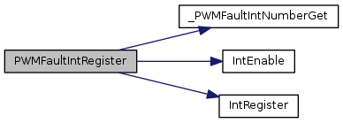
1647 {
1648  //
1649  // Check the arguments.
1650  //
1651  ASSERT((ui32Base == PWM0_BASE) || (ui32Base == PWM1_BASE));
1652  ASSERT((ui32FaultInts & ~(PWM_INT_FAULT0 | PWM_INT_FAULT1 |
1653  PWM_INT_FAULT2 | PWM_INT_FAULT3)) == 0);
1654 
1655  //
1656  // Clear the supplied fault bits.
1657  //
1658  HWREG(ui32Base + PWM_O_ISC) = ui32FaultInts;
1659 }
#define PWM1_BASE
Definition: hw_memmap.h:78
#define PWM_INT_FAULT2
Definition: pwm.h:125
#define HWREG(x)
Definition: hw_types.h:48
#define PWM_O_ISC
Definition: hw_pwm.h:55
#define ASSERT(expr)
Definition: debug.h:67
#define PWM_INT_FAULT3
Definition: pwm.h:126
#define PWM_INT_FAULT0
Definition: pwm.h:123
#define PWM_INT_FAULT1
Definition: pwm.h:124
#define PWM0_BASE
Definition: hw_memmap.h:77
void PWMFaultIntRegister ( uint32_t  ui32Base,
void(*)(void)  pfnIntHandler 
)

Registers an interrupt handler for a fault condition detected in a PWM module.

Parameters
ui32Baseis the base address of the PWM module.
pfnIntHandleris a pointer to the function to be called when the PWM fault interrupt occurs.

This function ensures that the interrupt handler specified by pfnIntHandler is called when a fault interrupt is detected for the selected PWM module. This function also enables the PWM fault interrupt in the NVIC; the PWM fault interrupt must also be enabled at the module level using PWMIntEnable().

See also
IntRegister() for important information about registering interrupt handlers.
Returns
None.

Definition at line 1221 of file pwm.c.

References _PWMFaultIntNumberGet(), ASSERT, IntEnable(), IntRegister(), PWM0_BASE, and PWM1_BASE.

1222 {
1223  uint32_t ui32Int;
1224 
1225  //
1226  // Check the arguments.
1227  //
1228  ASSERT((ui32Base == PWM0_BASE) || (ui32Base == PWM1_BASE));
1229 
1230  //
1231  // Get the interrupt number associated with the specified module.
1232  //
1233  ui32Int = _PWMFaultIntNumberGet(ui32Base);
1234 
1235  ASSERT(ui32Int != 0);
1236 
1237  //
1238  // Register the interrupt handler, returning an error if one occurs.
1239  //
1240  IntRegister(ui32Int, pfnIntHandler);
1241 
1242  //
1243  // Enable the PWM fault interrupt.
1244  //
1245  IntEnable(ui32Int);
1246 }
#define PWM1_BASE
Definition: hw_memmap.h:78
#define ASSERT(expr)
Definition: debug.h:67
static uint32_t _PWMFaultIntNumberGet(uint32_t ui32Base)
Definition: pwm.c:1179
#define PWM0_BASE
Definition: hw_memmap.h:77
void IntRegister(uint32_t ui32Interrupt, void(*pfnHandler)(void))
Definition: interrupt.c:309
void IntEnable(uint32_t ui32Interrupt)
Definition: interrupt.c:610

Here is the call graph for this function:

void PWMFaultIntUnregister ( uint32_t  ui32Base)

Removes the PWM fault condition interrupt handler.

Parameters
ui32Baseis the base address of the PWM module.

This function removes the interrupt handler for a PWM fault interrupt from the selected PWM module. This function also disables the PWM fault interrupt in the NVIC; the PWM fault interrupt must also be disabled at the module level using PWMIntDisable().

See also
IntRegister() for important information about registering interrupt handlers.
Returns
None.

Definition at line 1266 of file pwm.c.

References _PWMFaultIntNumberGet(), ASSERT, IntDisable(), IntUnregister(), PWM0_BASE, and PWM1_BASE.

1267 {
1268  uint32_t ui32Int;
1269 
1270  //
1271  // Check the arguments.
1272  //
1273  ASSERT((ui32Base == PWM0_BASE) || (ui32Base == PWM1_BASE));
1274 
1275  //
1276  // Get the interrupt number associated with the specified module.
1277  //
1278  ui32Int = _PWMFaultIntNumberGet(ui32Base);
1279 
1280  ASSERT(ui32Int != 0);
1281 
1282  //
1283  // Disable the PWM fault interrupt.
1284  //
1285  IntDisable(ui32Int);
1286 
1287  //
1288  // Unregister the interrupt handler, returning an error if one occurs.
1289  //
1290  IntUnregister(ui32Int);
1291 }
#define PWM1_BASE
Definition: hw_memmap.h:78
#define ASSERT(expr)
Definition: debug.h:67
static uint32_t _PWMFaultIntNumberGet(uint32_t ui32Base)
Definition: pwm.c:1179
void IntUnregister(uint32_t ui32Interrupt)
Definition: interrupt.c:381
#define PWM0_BASE
Definition: hw_memmap.h:77
void IntDisable(uint32_t ui32Interrupt)
Definition: interrupt.c:684

Here is the call graph for this function:

void PWMGenConfigure ( uint32_t  ui32Base,
uint32_t  ui32Gen,
uint32_t  ui32Config 
)

Configures a PWM generator.

Parameters
ui32Baseis the base address of the PWM module.
ui32Genis the PWM generator to configure. This parameter must be one of PWM_GEN_0, PWM_GEN_1, PWM_GEN_2, or PWM_GEN_3.
ui32Configis the configuration for the PWM generator.

This function is used to set the mode of operation for a PWM generator. The counting mode, synchronization mode, and debug behavior are all configured. After configuration, the generator is left in the disabled state.

A PWM generator can count in two different modes: count down mode or count up/down mode. In count down mode, it counts from a value down to zero, and then resets to the preset value, producing left-aligned PWM signals (that is, the rising edge of the two PWM signals produced by the generator occur at the same time). In count up/down mode, it counts up from zero to the preset value, counts back down to zero, and then repeats the process, producing center-aligned PWM signals (that is, the middle of the high/low period of the PWM signals produced by the generator occurs at the same time).

When the PWM generator parameters (period and pulse width) are modified, their effect on the output PWM signals can be delayed. In synchronous mode, the parameter updates are not applied until a synchronization event occurs. This mode allows multiple parameters to be modified and take effect simultaneously, instead of one at a time. Additionally, parameters to multiple PWM generators in synchronous mode can be updated simultaneously, allowing them to be treated as if they were a unified generator. In non-synchronous mode, the parameter updates are not delayed until a synchronization event. In either mode, the parameter updates only occur when the counter is at zero to help prevent oddly formed PWM signals during the update (that is, a PWM pulse that is too short or too long).

The PWM generator can either pause or continue running when the processor is stopped via the debugger. If configured to pause, it continues to count until it reaches zero, at which point it pauses until the processor is restarted. If configured to continue running, it keeps counting as if nothing had happened.

The ui32Config parameter contains the desired configuration. It is the logical OR of the following:

  • PWM_GEN_MODE_DOWN or PWM_GEN_MODE_UP_DOWN to specify the counting mode
  • PWM_GEN_MODE_SYNC or PWM_GEN_MODE_NO_SYNC to specify the counter load and comparator update synchronization mode
  • PWM_GEN_MODE_DBG_RUN or PWM_GEN_MODE_DBG_STOP to specify the debug behavior
  • PWM_GEN_MODE_GEN_NO_SYNC, PWM_GEN_MODE_GEN_SYNC_LOCAL, or PWM_GEN_MODE_GEN_SYNC_GLOBAL to specify the update synchronization mode for generator counting mode changes
  • PWM_GEN_MODE_DB_NO_SYNC, PWM_GEN_MODE_DB_SYNC_LOCAL, or PWM_GEN_MODE_DB_SYNC_GLOBAL to specify the deadband parameter synchronization mode
  • PWM_GEN_MODE_FAULT_LATCHED or PWM_GEN_MODE_FAULT_UNLATCHED to specify whether fault conditions are latched or not
  • PWM_GEN_MODE_FAULT_MINPER or PWM_GEN_MODE_FAULT_NO_MINPER to specify whether minimum fault period support is required
  • PWM_GEN_MODE_FAULT_EXT or PWM_GEN_MODE_FAULT_LEGACY to specify whether extended fault source selection support is enabled or not

Setting PWM_GEN_MODE_FAULT_MINPER allows an application to set the minimum duration of a PWM fault signal. Faults are signaled for at least this time even if the external fault pin deasserts earlier. Care should be taken when using this mode because during the fault signal period, the fault interrupt from the PWM generator remains asserted. The fault interrupt handler may, therefore, reenter immediately if it exits prior to expiration of the fault timer.

Note
Changes to the counter mode affect the period of the PWM signals produced. PWMGenPeriodSet() and PWMPulseWidthSet() should be called after any changes to the counter mode of a generator.
Returns
None.

Definition at line 200 of file pwm.c.

References ASSERT, HWREG, PWM0_BASE, PWM1_BASE, PWM_GEN_BADDR, PWM_O_X_CTL, PWM_O_X_GENA, PWM_O_X_GENB, PWM_X_CTL_CMPAUPD, PWM_X_CTL_CMPBUPD, PWM_X_CTL_DBCTLUPD_M, PWM_X_CTL_DBFALLUPD_M, PWM_X_CTL_DBRISEUPD_M, PWM_X_CTL_DEBUG, PWM_X_CTL_FLTSRC, PWM_X_CTL_GENAUPD_M, PWM_X_CTL_GENBUPD_M, PWM_X_CTL_LATCH, PWM_X_CTL_LOADUPD, PWM_X_CTL_MINFLTPER, PWM_X_CTL_MODE, PWM_X_GENA_ACTCMPAD_ZERO, PWM_X_GENA_ACTCMPAU_ONE, PWM_X_GENA_ACTLOAD_ONE, PWM_X_GENB_ACTCMPBD_ZERO, PWM_X_GENB_ACTCMPBU_ONE, and PWM_X_GENB_ACTLOAD_ONE.

202 {
203  //
204  // Check the arguments.
205  //
206  ASSERT((ui32Base == PWM0_BASE) || (ui32Base == PWM1_BASE));
207  ASSERT(_PWMGenValid(ui32Gen));
208 
209  //
210  // Compute the generator's base address.
211  //
212  ui32Gen = PWM_GEN_BADDR(ui32Base, ui32Gen);
213 
214  //
215  // Change the global configuration of the generator.
216  //
217  HWREG(ui32Gen + PWM_O_X_CTL) = ((HWREG(ui32Gen + PWM_O_X_CTL) &
227  PWM_X_CTL_CMPBUPD)) | ui32Config);
228 
229  //
230  // Set the individual PWM generator controls.
231  //
232  if(ui32Config & PWM_X_CTL_MODE)
233  {
234  //
235  // In up/down count mode, set the signal high on up count comparison
236  // and low on down count comparison (that is, center align the
237  // signals).
238  //
243  }
244  else
245  {
246  //
247  // In down count mode, set the signal high on load and low on count
248  // comparison (that is, left align the signals).
249  //
254  }
255 }
#define PWM1_BASE
Definition: hw_memmap.h:78
#define PWM_X_CTL_LOADUPD
Definition: hw_pwm.h:1603
#define PWM_X_CTL_FLTSRC
Definition: hw_pwm.h:1580
#define PWM_X_CTL_DBCTLUPD_M
Definition: hw_pwm.h:1589
#define PWM_GEN_BADDR(_mod_, _gen_)
Definition: pwm.c:64
#define PWM_X_GENA_ACTCMPAU_ONE
Definition: hw_pwm.h:1722
#define HWREG(x)
Definition: hw_types.h:48
#define PWM_X_CTL_LATCH
Definition: hw_pwm.h:1578
#define PWM_X_GENB_ACTLOAD_ONE
Definition: hw_pwm.h:1771
#define PWM_X_CTL_MINFLTPER
Definition: hw_pwm.h:1579
#define ASSERT(expr)
Definition: debug.h:67
#define PWM_X_CTL_GENBUPD_M
Definition: hw_pwm.h:1593
#define PWM_X_CTL_DBRISEUPD_M
Definition: hw_pwm.h:1585
#define PWM_X_CTL_CMPAUPD
Definition: hw_pwm.h:1602
#define PWM_X_CTL_DBFALLUPD_M
Definition: hw_pwm.h:1581
#define PWM_X_GENA_ACTCMPAD_ZERO
Definition: hw_pwm.h:1713
#define PWM_O_X_GENB
Definition: hw_pwm.h:1561
#define PWM_X_GENB_ACTCMPBU_ONE
Definition: hw_pwm.h:1752
#define PWM_X_CTL_GENAUPD_M
Definition: hw_pwm.h:1597
#define PWM_O_X_GENA
Definition: hw_pwm.h:1560
#define PWM_X_CTL_MODE
Definition: hw_pwm.h:1605
#define PWM_X_CTL_CMPBUPD
Definition: hw_pwm.h:1601
#define PWM_X_GENA_ACTLOAD_ONE
Definition: hw_pwm.h:1727
#define PWM_X_CTL_DEBUG
Definition: hw_pwm.h:1604
#define PWM0_BASE
Definition: hw_memmap.h:77
#define PWM_X_GENB_ACTCMPBD_ZERO
Definition: hw_pwm.h:1743
#define PWM_O_X_CTL
Definition: hw_pwm.h:1552
void PWMGenDisable ( uint32_t  ui32Base,
uint32_t  ui32Gen 
)

Disables the timer/counter for a PWM generator block.

Parameters
ui32Baseis the base address of the PWM module.
ui32Genis the PWM generator to be disabled. This parameter must be one of PWM_GEN_0, PWM_GEN_1, PWM_GEN_2, or PWM_GEN_3.

This function blocks the PWM clock from driving the timer/counter for the specified generator block.

Returns
None.

Definition at line 412 of file pwm.c.

References ASSERT, HWREG, PWM0_BASE, PWM1_BASE, PWM_GEN_BADDR, PWM_O_X_CTL, and PWM_X_CTL_ENABLE.

413 {
414  //
415  // Check the arguments.
416  //
417  ASSERT((ui32Base == PWM0_BASE) || (ui32Base == PWM1_BASE));
418  ASSERT(_PWMGenValid(ui32Gen));
419 
420  //
421  // Disable the PWM generator.
422  //
423  HWREG(PWM_GEN_BADDR(ui32Base, ui32Gen) + PWM_O_X_CTL) &=
424  ~(PWM_X_CTL_ENABLE);
425 }
#define PWM1_BASE
Definition: hw_memmap.h:78
#define PWM_GEN_BADDR(_mod_, _gen_)
Definition: pwm.c:64
#define HWREG(x)
Definition: hw_types.h:48
#define ASSERT(expr)
Definition: debug.h:67
#define PWM_X_CTL_ENABLE
Definition: hw_pwm.h:1606
#define PWM0_BASE
Definition: hw_memmap.h:77
#define PWM_O_X_CTL
Definition: hw_pwm.h:1552
void PWMGenEnable ( uint32_t  ui32Base,
uint32_t  ui32Gen 
)

Enables the timer/counter for a PWM generator block.

Parameters
ui32Baseis the base address of the PWM module.
ui32Genis the PWM generator to be enabled. This parameter must be one of PWM_GEN_0, PWM_GEN_1, PWM_GEN_2, or PWM_GEN_3.

This function allows the PWM clock to drive the timer/counter for the specified generator block.

Returns
None.

Definition at line 383 of file pwm.c.

References ASSERT, HWREG, PWM0_BASE, PWM1_BASE, PWM_GEN_BADDR, PWM_O_X_CTL, and PWM_X_CTL_ENABLE.

384 {
385  //
386  // Check the arguments.
387  //
388  ASSERT((ui32Base == PWM0_BASE) || (ui32Base == PWM1_BASE));
389  ASSERT(_PWMGenValid(ui32Gen));
390 
391  //
392  // Enable the PWM generator.
393  //
394  HWREG(PWM_GEN_BADDR(ui32Base, ui32Gen) + PWM_O_X_CTL) |= PWM_X_CTL_ENABLE;
395 }
#define PWM1_BASE
Definition: hw_memmap.h:78
#define PWM_GEN_BADDR(_mod_, _gen_)
Definition: pwm.c:64
#define HWREG(x)
Definition: hw_types.h:48
#define ASSERT(expr)
Definition: debug.h:67
#define PWM_X_CTL_ENABLE
Definition: hw_pwm.h:1606
#define PWM0_BASE
Definition: hw_memmap.h:77
#define PWM_O_X_CTL
Definition: hw_pwm.h:1552
void PWMGenFaultClear ( uint32_t  ui32Base,
uint32_t  ui32Gen,
uint32_t  ui32Group,
uint32_t  ui32FaultTriggers 
)

Clears one or more latched fault triggers for a given PWM generator.

Parameters
ui32Baseis the base address of the PWM module.
ui32Genis the PWM generator for which fault trigger states are being queried. This parameter must be one of PWM_GEN_0, PWM_GEN_1, PWM_GEN_2, or PWM_GEN_3.
ui32Groupindicates the subset of faults that are being queried. This parameter must be PWM_FAULT_GROUP_0 or PWM_FAULT_GROUP_1.
ui32FaultTriggersis the set of fault triggers which are to be cleared.

This function allows an application to clear the fault triggers for a given PWM generator. This function is only required if PWMGenConfigure() has previously been called with flag PWM_GEN_MODE_FAULT_LATCHED in parameter ui32Config.

Note
This function is only available on devices supporting extended PWM fault handling.
Returns
None.

Definition at line 1930 of file pwm.c.

References ASSERT, HWREG, PWM0_BASE, PWM1_BASE, PWM_FAULT_DCMP0, PWM_FAULT_DCMP1, PWM_FAULT_DCMP2, PWM_FAULT_DCMP3, PWM_FAULT_DCMP4, PWM_FAULT_DCMP5, PWM_FAULT_DCMP6, PWM_FAULT_DCMP7, PWM_FAULT_FAULT0, PWM_FAULT_FAULT1, PWM_FAULT_FAULT2, PWM_FAULT_FAULT3, PWM_FAULT_GROUP_0, PWM_FAULT_GROUP_1, PWM_GEN_EXT_BADDR, PWM_O_X_FLTSTAT0, and PWM_O_X_FLTSTAT1.

1932 {
1933  //
1934  // Check for valid parameters.
1935  //
1936  ASSERT((ui32Base == PWM0_BASE) || (ui32Base == PWM1_BASE));
1937  ASSERT(_PWMGenValid(ui32Gen));
1938  ASSERT((ui32Group == PWM_FAULT_GROUP_0) ||
1939  (ui32Group == PWM_FAULT_GROUP_1));
1940  ASSERT((ui32Group == PWM_FAULT_GROUP_0) &&
1941  ((ui32FaultTriggers & ~(PWM_FAULT_FAULT0 | PWM_FAULT_FAULT1 |
1943  0));
1944  ASSERT((ui32Group == PWM_FAULT_GROUP_1) &&
1945  ((ui32FaultTriggers & ~(PWM_FAULT_DCMP0 | PWM_FAULT_DCMP1 |
1948  PWM_FAULT_DCMP6 | PWM_FAULT_DCMP7)) == 0));
1949 
1950  //
1951  // Clear the given faults.
1952  //
1953  if(ui32Group == PWM_FAULT_GROUP_0)
1954  {
1955  HWREG(PWM_GEN_EXT_BADDR(ui32Base, ui32Gen) + PWM_O_X_FLTSTAT0) =
1956  ui32FaultTriggers;
1957  }
1958  else
1959  {
1960  HWREG(PWM_GEN_EXT_BADDR(ui32Base, ui32Gen) + PWM_O_X_FLTSTAT1) =
1961  ui32FaultTriggers;
1962  }
1963 }
#define PWM_FAULT_DCMP5
Definition: pwm.h:201
#define PWM1_BASE
Definition: hw_memmap.h:78
#define PWM_FAULT_DCMP4
Definition: pwm.h:200
#define HWREG(x)
Definition: hw_types.h:48
#define PWM_GEN_EXT_BADDR(_mod_, _gen_)
Definition: pwm.c:66
#define PWM_FAULT_GROUP_1
Definition: pwm.h:194
#define ASSERT(expr)
Definition: debug.h:67
#define PWM_FAULT_FAULT1
Definition: pwm.h:181
#define PWM_FAULT_DCMP3
Definition: pwm.h:199
#define PWM_FAULT_DCMP1
Definition: pwm.h:197
#define PWM_FAULT_FAULT0
Definition: pwm.h:180
#define PWM_FAULT_DCMP2
Definition: pwm.h:198
#define PWM_O_X_FLTSTAT0
Definition: hw_pwm.h:1842
#define PWM_FAULT_GROUP_0
Definition: pwm.h:178
#define PWM_FAULT_FAULT3
Definition: pwm.h:183
#define PWM0_BASE
Definition: hw_memmap.h:77
#define PWM_FAULT_DCMP6
Definition: pwm.h:202
#define PWM_O_X_FLTSTAT1
Definition: hw_pwm.h:1843
#define PWM_FAULT_DCMP7
Definition: pwm.h:203
#define PWM_FAULT_DCMP0
Definition: pwm.h:196
#define PWM_FAULT_FAULT2
Definition: pwm.h:182
void PWMGenFaultConfigure ( uint32_t  ui32Base,
uint32_t  ui32Gen,
uint32_t  ui32MinFaultPeriod,
uint32_t  ui32FaultSenses 
)

Configures the minimum fault period and fault pin senses for a given PWM generator.

Parameters
ui32Baseis the base address of the PWM module.
ui32Genis the PWM generator for which fault configuration is being set. This function must be one of PWM_GEN_0, PWM_GEN_1, PWM_GEN_2, or PWM_GEN_3.
ui32MinFaultPeriodis the minimum fault active period expressed in PWM clock cycles.
ui32FaultSensesindicates which sense of each FAULT input should be considered the ``asserted'' state. Valid values are logical OR combinations of PWM_FAULTn_SENSE_HIGH and PWM_FAULTn_SENSE_LOW.

This function configures the minimum fault period for a given generator along with the sense of each of the 4 possible fault inputs. The minimum fault period is expressed in PWM clock cycles and takes effect only if PWMGenConfigure() is called with flag PWM_GEN_MODE_FAULT_PER set in the ui32Config parameter. When a fault input is asserted, the minimum fault period timer ensures that it remains asserted for at least the number of clock cycles specified.

Note
This function is only available on devices supporting extended PWM fault handling.
Returns
None.

Definition at line 1691 of file pwm.c.

References ASSERT, HWREG, PWM0_BASE, PWM1_BASE, PWM_FAULT0_SENSE_HIGH, PWM_FAULT0_SENSE_LOW, PWM_FAULT1_SENSE_HIGH, PWM_FAULT1_SENSE_LOW, PWM_FAULT2_SENSE_HIGH, PWM_FAULT2_SENSE_LOW, PWM_FAULT3_SENSE_HIGH, PWM_FAULT3_SENSE_LOW, PWM_GEN_BADDR, PWM_GEN_EXT_BADDR, PWM_O_X_FLTSEN, PWM_O_X_MINFLTPER, and PWM_X_MINFLTPER_M.

1694 {
1695  //
1696  // Check the arguments.
1697  //
1698  ASSERT((ui32Base == PWM0_BASE) || (ui32Base == PWM1_BASE));
1699  ASSERT(_PWMGenValid(ui32Gen));
1700  ASSERT(ui32MinFaultPeriod < PWM_X_MINFLTPER_M);
1701  ASSERT((ui32FaultSenses & ~(PWM_FAULT0_SENSE_HIGH | PWM_FAULT0_SENSE_LOW |
1705  PWM_FAULT3_SENSE_LOW)) == 0);
1706 
1707  //
1708  // Write the minimum fault period.
1709  //
1710  HWREG(PWM_GEN_BADDR(ui32Base, ui32Gen) + PWM_O_X_MINFLTPER) =
1711  ui32MinFaultPeriod;
1712 
1713  //
1714  // Write the fault senses.
1715  //
1716  HWREG(PWM_GEN_EXT_BADDR(ui32Base, ui32Gen) + PWM_O_X_FLTSEN) =
1717  ui32FaultSenses;
1718 }
#define PWM1_BASE
Definition: hw_memmap.h:78
#define PWM_GEN_BADDR(_mod_, _gen_)
Definition: pwm.c:64
#define HWREG(x)
Definition: hw_types.h:48
#define PWM_GEN_EXT_BADDR(_mod_, _gen_)
Definition: pwm.c:66
#define PWM_O_X_MINFLTPER
Definition: hw_pwm.h:1567
#define PWM_FAULT3_SENSE_LOW
Definition: pwm.h:217
#define PWM_FAULT0_SENSE_HIGH
Definition: pwm.h:210
#define ASSERT(expr)
Definition: debug.h:67
#define PWM_O_X_FLTSEN
Definition: hw_pwm.h:1841
#define PWM_FAULT2_SENSE_LOW
Definition: pwm.h:215
#define PWM_FAULT1_SENSE_LOW
Definition: pwm.h:213
#define PWM_X_MINFLTPER_M
Definition: hw_pwm.h:1833
#define PWM_FAULT2_SENSE_HIGH
Definition: pwm.h:214
#define PWM_FAULT1_SENSE_HIGH
Definition: pwm.h:212
#define PWM_FAULT3_SENSE_HIGH
Definition: pwm.h:216
#define PWM_FAULT0_SENSE_LOW
Definition: pwm.h:211
#define PWM0_BASE
Definition: hw_memmap.h:77
uint32_t PWMGenFaultStatus ( uint32_t  ui32Base,
uint32_t  ui32Gen,
uint32_t  ui32Group 
)

Returns the current state of the fault triggers for a given PWM generator.

Parameters
ui32Baseis the base address of the PWM module.
ui32Genis the PWM generator for which fault trigger states are being queried. This parameter must be one of PWM_GEN_0, PWM_GEN_1, PWM_GEN_2, or PWM_GEN_3.
ui32Groupindicates the subset of faults that are being queried. This parameter must be PWM_FAULT_GROUP_0 or PWM_FAULT_GROUP_1.

This function allows an application to query the current state of each of the fault trigger inputs to a given PWM generator. The current state of each fault trigger input is returned unless PWMGenConfigure() has previously been called with flag PWM_GEN_MODE_FAULT_LATCHED in the ui32Config parameter, in which case the returned status is the latched fault trigger status.

If latched faults are configured, the application must call PWMGenFaultClear() to clear each trigger.

Note
This function is only available on devices supporting extended PWM fault handling.
Returns
Returns the current state of the fault triggers for the given PWM generator. A set bit indicates that the associated trigger is active. For PWM_FAULT_GROUP_0, the returned value is a logical OR of PWM_FAULT_FAULT0, PWM_FAULT_FAULT1, PWM_FAULT_FAULT2, or PWM_FAULT_FAULT3. For PWM_FAULT_GROUP_1, the return value is the logical OR of PWM_FAULT_DCMP0, PWM_FAULT_DCMP1, PWM_FAULT_DCMP2, PWM_FAULT_DCMP3, PWM_FAULT_DCMP4, PWM_FAULT_DCMP5, PWM_FAULT_DCMP6, or PWM_FAULT_DCMP7.

Definition at line 1881 of file pwm.c.

References ASSERT, HWREG, PWM0_BASE, PWM1_BASE, PWM_FAULT_GROUP_0, PWM_FAULT_GROUP_1, PWM_GEN_EXT_BADDR, PWM_O_X_FLTSTAT0, and PWM_O_X_FLTSTAT1.

1883 {
1884  //
1885  // Check for valid parameters.
1886  //
1887  ASSERT((ui32Base == PWM0_BASE) || (ui32Base == PWM1_BASE));
1888  ASSERT(_PWMGenValid(ui32Gen));
1889  ASSERT((ui32Group == PWM_FAULT_GROUP_0) ||
1890  (ui32Group == PWM_FAULT_GROUP_1));
1891 
1892  //
1893  // Return the current fault status.
1894  //
1895  if(ui32Group == PWM_FAULT_GROUP_0)
1896  {
1897  return(HWREG(PWM_GEN_EXT_BADDR(ui32Base, ui32Gen) + PWM_O_X_FLTSTAT0));
1898  }
1899  else
1900  {
1901  return(HWREG(PWM_GEN_EXT_BADDR(ui32Base, ui32Gen) + PWM_O_X_FLTSTAT1));
1902  }
1903 }
#define PWM1_BASE
Definition: hw_memmap.h:78
#define HWREG(x)
Definition: hw_types.h:48
#define PWM_GEN_EXT_BADDR(_mod_, _gen_)
Definition: pwm.c:66
#define PWM_FAULT_GROUP_1
Definition: pwm.h:194
#define ASSERT(expr)
Definition: debug.h:67
#define PWM_O_X_FLTSTAT0
Definition: hw_pwm.h:1842
#define PWM_FAULT_GROUP_0
Definition: pwm.h:178
#define PWM0_BASE
Definition: hw_memmap.h:77
#define PWM_O_X_FLTSTAT1
Definition: hw_pwm.h:1843
uint32_t PWMGenFaultTriggerGet ( uint32_t  ui32Base,
uint32_t  ui32Gen,
uint32_t  ui32Group 
)

Returns the set of fault triggers currently configured for a given PWM generator.

Parameters
ui32Baseis the base address of the PWM module.
ui32Genis the PWM generator for which fault triggers are being queried. This parameter must be one of PWM_GEN_0, PWM_GEN_1, PWM_GEN_2, or PWM_GEN_3.
ui32Groupindicates the subset of faults that are being queried. This parameter must be PWM_FAULT_GROUP_0 or PWM_FAULT_GROUP_1.

This function allows an application to query the current set of inputs that contribute to the generation of a fault condition to a given PWM generator.

Note
This function is only available on devices supporting extended PWM fault handling.
Returns
Returns the current fault triggers configured for the fault group provided. For PWM_FAULT_GROUP_0, the returned value is a logical OR of PWM_FAULT_FAULT0, PWM_FAULT_FAULT1, PWM_FAULT_FAULT2, or PWM_FAULT_FAULT3. For PWM_FAULT_GROUP_1, the return value is the logical OR of PWM_FAULT_DCMP0, PWM_FAULT_DCMP1, PWM_FAULT_DCMP2, PWM_FAULT_DCMP3, PWM_FAULT_DCMP4, PWM_FAULT_DCMP5, PWM_FAULT_DCMP6, or PWM_FAULT_DCMP7.

Definition at line 1822 of file pwm.c.

References ASSERT, HWREG, PWM0_BASE, PWM1_BASE, PWM_FAULT_GROUP_0, PWM_FAULT_GROUP_1, PWM_GEN_BADDR, PWM_O_X_FLTSRC0, and PWM_O_X_FLTSRC1.

1824 {
1825  //
1826  // Check for valid parameters.
1827  //
1828  ASSERT((ui32Base == PWM0_BASE) || (ui32Base == PWM1_BASE));
1829  ASSERT(_PWMGenValid(ui32Gen));
1830  ASSERT((ui32Group == PWM_FAULT_GROUP_0) ||
1831  (ui32Group == PWM_FAULT_GROUP_1));
1832 
1833  //
1834  // Return the current fault triggers.
1835  //
1836  if(ui32Group == PWM_FAULT_GROUP_0)
1837  {
1838  return(HWREG(PWM_GEN_BADDR(ui32Base, ui32Gen) + PWM_O_X_FLTSRC0));
1839  }
1840  else
1841  {
1842  return(HWREG(PWM_GEN_BADDR(ui32Base, ui32Gen) + PWM_O_X_FLTSRC1));
1843  }
1844 }
#define PWM1_BASE
Definition: hw_memmap.h:78
#define PWM_GEN_BADDR(_mod_, _gen_)
Definition: pwm.c:64
#define HWREG(x)
Definition: hw_types.h:48
#define PWM_FAULT_GROUP_1
Definition: pwm.h:194
#define ASSERT(expr)
Definition: debug.h:67
#define PWM_O_X_FLTSRC0
Definition: hw_pwm.h:1565
#define PWM_FAULT_GROUP_0
Definition: pwm.h:178
#define PWM_O_X_FLTSRC1
Definition: hw_pwm.h:1566
#define PWM0_BASE
Definition: hw_memmap.h:77
void PWMGenFaultTriggerSet ( uint32_t  ui32Base,
uint32_t  ui32Gen,
uint32_t  ui32Group,
uint32_t  ui32FaultTriggers 
)

Configures the set of fault triggers for a given PWM generator.

Parameters
ui32Baseis the base address of the PWM module.
ui32Genis the PWM generator for which fault triggers are being set. This parameter must be one of PWM_GEN_0, PWM_GEN_1, PWM_GEN_2, or PWM_GEN_3.
ui32Groupindicates the subset of possible faults that are to be configured. This parameter must be PWM_FAULT_GROUP_0 or PWM_FAULT_GROUP_1.
ui32FaultTriggersdefines the set of inputs that are to contribute towards generation of the fault signal to the given PWM generator. For PWM_FAULT_GROUP_0, this is the logical OR of PWM_FAULT_FAULT0, PWM_FAULT_FAULT1, PWM_FAULT_FAULT2, or PWM_FAULT_FAULT3. For PWM_FAULT_GROUP_1, this is the logical OR of PWM_FAULT_DCMP0, PWM_FAULT_DCMP1, PWM_FAULT_DCMP2, PWM_FAULT_DCMP3, PWM_FAULT_DCMP4, PWM_FAULT_DCMP5, PWM_FAULT_DCMP6, or PWM_FAULT_DCMP7.

This function allows selection of the set of fault inputs that is combined to generate a fault condition to a given PWM generator. By default, all generators use only FAULT0 (for backwards compatibility) but if PWMGenConfigure() is called with flag PWM_GEN_MODE_FAULT_SRC in the ui32Config parameter, extended fault handling is enabled and this function must be called to configure the fault triggers.

The fault signal to the PWM generator is generated by ORing together each of the signals specified in the ui32FaultTriggers parameter after having adjusted the sense of each FAULTn input based on the configuration previously set using a call to PWMGenFaultConfigure().

Note
This function is only available on devices supporting extended PWM fault handling.
Returns
None.

Definition at line 1759 of file pwm.c.

References ASSERT, HWREG, PWM0_BASE, PWM1_BASE, PWM_FAULT_DCMP0, PWM_FAULT_DCMP1, PWM_FAULT_DCMP2, PWM_FAULT_DCMP3, PWM_FAULT_DCMP4, PWM_FAULT_DCMP5, PWM_FAULT_DCMP6, PWM_FAULT_DCMP7, PWM_FAULT_FAULT0, PWM_FAULT_FAULT1, PWM_FAULT_FAULT2, PWM_FAULT_FAULT3, PWM_FAULT_GROUP_0, PWM_FAULT_GROUP_1, PWM_GEN_BADDR, PWM_O_X_FLTSRC0, and PWM_O_X_FLTSRC1.

1761 {
1762  //
1763  // Check for valid parameters.
1764  //
1765  ASSERT((ui32Base == PWM0_BASE) || (ui32Base == PWM1_BASE));
1766  ASSERT(_PWMGenValid(ui32Gen));
1767  ASSERT((ui32Group == PWM_FAULT_GROUP_0) ||
1768  (ui32Group == PWM_FAULT_GROUP_1));
1769  ASSERT((ui32Group == PWM_FAULT_GROUP_0) &&
1770  ((ui32FaultTriggers & ~(PWM_FAULT_FAULT0 | PWM_FAULT_FAULT1 |
1772  0));
1773  ASSERT((ui32Group == PWM_FAULT_GROUP_1) &&
1774  ((ui32FaultTriggers & ~(PWM_FAULT_DCMP0 | PWM_FAULT_DCMP1 |
1777  PWM_FAULT_DCMP6 | PWM_FAULT_DCMP7)) == 0));
1778 
1779  //
1780  // Write the fault triggers to the appropriate register.
1781  //
1782  if(ui32Group == PWM_FAULT_GROUP_0)
1783  {
1784  HWREG(PWM_GEN_BADDR(ui32Base, ui32Gen) + PWM_O_X_FLTSRC0) =
1785  ui32FaultTriggers;
1786  }
1787  else
1788  {
1789  HWREG(PWM_GEN_BADDR(ui32Base, ui32Gen) + PWM_O_X_FLTSRC1) =
1790  ui32FaultTriggers;
1791  }
1792 }
#define PWM_FAULT_DCMP5
Definition: pwm.h:201
#define PWM1_BASE
Definition: hw_memmap.h:78
#define PWM_FAULT_DCMP4
Definition: pwm.h:200
#define PWM_GEN_BADDR(_mod_, _gen_)
Definition: pwm.c:64
#define HWREG(x)
Definition: hw_types.h:48
#define PWM_FAULT_GROUP_1
Definition: pwm.h:194
#define ASSERT(expr)
Definition: debug.h:67
#define PWM_O_X_FLTSRC0
Definition: hw_pwm.h:1565
#define PWM_FAULT_FAULT1
Definition: pwm.h:181
#define PWM_FAULT_DCMP3
Definition: pwm.h:199
#define PWM_FAULT_DCMP1
Definition: pwm.h:197
#define PWM_FAULT_FAULT0
Definition: pwm.h:180
#define PWM_FAULT_DCMP2
Definition: pwm.h:198
#define PWM_FAULT_GROUP_0
Definition: pwm.h:178
#define PWM_O_X_FLTSRC1
Definition: hw_pwm.h:1566
#define PWM_FAULT_FAULT3
Definition: pwm.h:183
#define PWM0_BASE
Definition: hw_memmap.h:77
#define PWM_FAULT_DCMP6
Definition: pwm.h:202
#define PWM_FAULT_DCMP7
Definition: pwm.h:203
#define PWM_FAULT_DCMP0
Definition: pwm.h:196
#define PWM_FAULT_FAULT2
Definition: pwm.h:182
void PWMGenIntClear ( uint32_t  ui32Base,
uint32_t  ui32Gen,
uint32_t  ui32Ints 
)

Clears the specified interrupt(s) for the specified PWM generator block.

Parameters
ui32Baseis the base address of the PWM module.
ui32Genis the PWM generator to query. This parameter must be one of PWM_GEN_0, PWM_GEN_1, PWM_GEN_2, or PWM_GEN_3.
ui32Intsspecifies the interrupts to be cleared.

This function clears the specified interrupt(s) by writing a 1 to the specified bits of the interrupt status register for the specified PWM generator. The ui32Ints parameter is the logical OR of PWM_INT_CNT_ZERO, PWM_INT_CNT_LOAD, PWM_INT_CNT_AU, PWM_INT_CNT_AD, PWM_INT_CNT_BU, or PWM_INT_CNT_BD.

Note
Because there is a write buffer in the Cortex-M processor, it may take several clock cycles before the interrupt source is actually cleared. Therefore, it is recommended that the interrupt source be cleared early in the interrupt handler (as opposed to the very last action) to avoid returning from the interrupt handler before the interrupt source is actually cleared. Failure to do so may result in the interrupt handler being immediately reentered (because the interrupt controller still sees the interrupt source asserted).
Returns
None.

Definition at line 1451 of file pwm.c.

References ASSERT, HWREG, PWM0_BASE, PWM1_BASE, PWM_GEN_BADDR, PWM_INT_CNT_AD, PWM_INT_CNT_AU, PWM_INT_CNT_BD, PWM_INT_CNT_BU, PWM_INT_CNT_LOAD, PWM_INT_CNT_ZERO, and PWM_O_X_ISC.

1452 {
1453  //
1454  // Check the arguments.
1455  //
1456  ASSERT((ui32Base == PWM0_BASE) || (ui32Base == PWM1_BASE));
1457  ASSERT(_PWMGenValid(ui32Gen));
1458  ASSERT((ui32Ints &
1461 
1462  //
1463  // Clear the requested interrupts by writing ones to the specified bit
1464  // of the module's interrupt enable register.
1465  //
1466  HWREG(PWM_GEN_BADDR(ui32Base, ui32Gen) + PWM_O_X_ISC) = ui32Ints;
1467 }
#define PWM1_BASE
Definition: hw_memmap.h:78
#define PWM_INT_CNT_LOAD
Definition: pwm.h:102
#define PWM_INT_CNT_AU
Definition: pwm.h:103
#define PWM_GEN_BADDR(_mod_, _gen_)
Definition: pwm.c:64
#define HWREG(x)
Definition: hw_types.h:48
#define ASSERT(expr)
Definition: debug.h:67
#define PWM_INT_CNT_AD
Definition: pwm.h:104
#define PWM_INT_CNT_BD
Definition: pwm.h:106
#define PWM_O_X_ISC
Definition: hw_pwm.h:1555
#define PWM_INT_CNT_BU
Definition: pwm.h:105
#define PWM0_BASE
Definition: hw_memmap.h:77
#define PWM_INT_CNT_ZERO
Definition: pwm.h:101
void PWMGenIntRegister ( uint32_t  ui32Base,
uint32_t  ui32Gen,
void(*)(void)  pfnIntHandler 
)

Registers an interrupt handler for the specified PWM generator block.

Parameters
ui32Baseis the base address of the PWM module.
ui32Genis the PWM generator in question. This parameter must be one of PWM_GEN_0, PWM_GEN_1, PWM_GEN_2, or PWM_GEN_3.
pfnIntHandleris a pointer to the function to be called when the PWM generator interrupt occurs.

This function ensures that the interrupt handler specified by pfnIntHandler is called when an interrupt is detected for the specified PWM generator block. This function also enables the corresponding PWM generator interrupt in the interrupt controller; individual generator interrupts and interrupt sources must be enabled with PWMIntEnable() and PWMGenIntTrigEnable().

See also
IntRegister() for important information about registering interrupt handlers.
Returns
None.

Definition at line 1088 of file pwm.c.

References _PWMGenIntNumberGet(), ASSERT, IntEnable(), IntRegister(), PWM0_BASE, and PWM1_BASE.

1090 {
1091  uint32_t ui32Int;
1092 
1093  //
1094  // Check the arguments.
1095  //
1096  ASSERT((ui32Base == PWM0_BASE) || (ui32Base == PWM1_BASE));
1097  ASSERT(_PWMGenValid(ui32Gen));
1098 
1099  //
1100  // Get the interrupt number associated with the specified generator.
1101  //
1102  ui32Int = _PWMGenIntNumberGet(ui32Base, ui32Gen);
1103 
1104  ASSERT(ui32Int != 0);
1105 
1106  //
1107  // Register the interrupt handler.
1108  //
1109  IntRegister(ui32Int, pfnIntHandler);
1110 
1111  //
1112  // Enable the PWMx interrupt.
1113  //
1114  IntEnable(ui32Int);
1115 }
#define PWM1_BASE
Definition: hw_memmap.h:78
static uint32_t _PWMGenIntNumberGet(uint32_t ui32Base, uint32_t ui32Gen)
Definition: pwm.c:923
#define ASSERT(expr)
Definition: debug.h:67
#define PWM0_BASE
Definition: hw_memmap.h:77
void IntRegister(uint32_t ui32Interrupt, void(*pfnHandler)(void))
Definition: interrupt.c:309
void IntEnable(uint32_t ui32Interrupt)
Definition: interrupt.c:610

Here is the call graph for this function:

uint32_t PWMGenIntStatus ( uint32_t  ui32Base,
uint32_t  ui32Gen,
bool  bMasked 
)

Gets interrupt status for the specified PWM generator block.

Parameters
ui32Baseis the base address of the PWM module.
ui32Genis the PWM generator to query. This parameter must be one of PWM_GEN_0, PWM_GEN_1, PWM_GEN_2, or PWM_GEN_3.
bMaskedspecifies whether masked or raw interrupt status is returned.

If bMasked is set as true, then the masked interrupt status is returned; otherwise, the raw interrupt status is returned.

Returns
Returns the contents of the interrupt status register or the contents of the raw interrupt status register for the specified PWM generator.

Definition at line 1396 of file pwm.c.

References ASSERT, HWREG, PWM0_BASE, PWM1_BASE, PWM_GEN_BADDR, PWM_O_X_ISC, and PWM_O_X_RIS.

1397 {
1398  //
1399  // Check the arguments.
1400  //
1401  ASSERT((ui32Base == PWM0_BASE) || (ui32Base == PWM1_BASE));
1402  ASSERT(_PWMGenValid(ui32Gen));
1403 
1404  //
1405  // Compute the generator's base address.
1406  //
1407  ui32Gen = PWM_GEN_BADDR(ui32Base, ui32Gen);
1408 
1409  //
1410  // Read and return the specified generator's raw or enabled interrupt
1411  // status.
1412  //
1413  if(bMasked == true)
1414  {
1415  return(HWREG(ui32Gen + PWM_O_X_ISC));
1416  }
1417  else
1418  {
1419  return(HWREG(ui32Gen + PWM_O_X_RIS));
1420  }
1421 }
#define PWM1_BASE
Definition: hw_memmap.h:78
#define PWM_GEN_BADDR(_mod_, _gen_)
Definition: pwm.c:64
#define HWREG(x)
Definition: hw_types.h:48
#define ASSERT(expr)
Definition: debug.h:67
#define PWM_O_X_ISC
Definition: hw_pwm.h:1555
#define PWM_O_X_RIS
Definition: hw_pwm.h:1554
#define PWM0_BASE
Definition: hw_memmap.h:77
void PWMGenIntTrigDisable ( uint32_t  ui32Base,
uint32_t  ui32Gen,
uint32_t  ui32IntTrig 
)

Disables interrupts for the specified PWM generator block.

Parameters
ui32Baseis the base address of the PWM module.
ui32Genis the PWM generator to have interrupts and triggers disabled. This parameter must be one of PWM_GEN_0, PWM_GEN_1, PWM_GEN_2, or PWM_GEN_3.
ui32IntTrigspecifies the interrupts and triggers to be disabled.

This function masks the specified interrupt(s) and trigger(s) by clearing the specified bits of the interrupt/trigger enable register for the specified PWM generator. The ui32IntTrig parameter is the logical OR of PWM_INT_CNT_ZERO, PWM_INT_CNT_LOAD, PWM_INT_CNT_AU, PWM_INT_CNT_AD, PWM_INT_CNT_BU, PWM_INT_CNT_BD, PWM_TR_CNT_ZERO, PWM_TR_CNT_LOAD, PWM_TR_CNT_AU, PWM_TR_CNT_AD, PWM_TR_CNT_BU, or PWM_TR_CNT_BD.

Returns
None.

Definition at line 1357 of file pwm.c.

References ASSERT, HWREG, PWM0_BASE, PWM1_BASE, PWM_GEN_BADDR, PWM_INT_CNT_AD, PWM_INT_CNT_AU, PWM_INT_CNT_BD, PWM_INT_CNT_BU, PWM_INT_CNT_LOAD, PWM_INT_CNT_ZERO, PWM_O_X_INTEN, PWM_TR_CNT_AD, PWM_TR_CNT_AU, PWM_TR_CNT_BD, PWM_TR_CNT_BU, PWM_TR_CNT_LOAD, and PWM_TR_CNT_ZERO.

1359 {
1360  //
1361  // Check the arguments.
1362  //
1363  ASSERT((ui32Base == PWM0_BASE) || (ui32Base == PWM1_BASE));
1364  ASSERT(_PWMGenValid(ui32Gen));
1365  ASSERT((ui32IntTrig & ~(PWM_INT_CNT_ZERO | PWM_INT_CNT_LOAD |
1369  PWM_TR_CNT_BU | PWM_TR_CNT_BD)) == 0);
1370 
1371  //
1372  // Disable the specified interrupts/triggers.
1373  //
1374  HWREG(PWM_GEN_BADDR(ui32Base, ui32Gen) + PWM_O_X_INTEN) &= ~(ui32IntTrig);
1375 }
#define PWM1_BASE
Definition: hw_memmap.h:78
#define PWM_TR_CNT_LOAD
Definition: pwm.h:108
#define PWM_INT_CNT_LOAD
Definition: pwm.h:102
#define PWM_INT_CNT_AU
Definition: pwm.h:103
#define PWM_GEN_BADDR(_mod_, _gen_)
Definition: pwm.c:64
#define HWREG(x)
Definition: hw_types.h:48
#define ASSERT(expr)
Definition: debug.h:67
#define PWM_INT_CNT_AD
Definition: pwm.h:104
#define PWM_O_X_INTEN
Definition: hw_pwm.h:1553
#define PWM_TR_CNT_AD
Definition: pwm.h:110
#define PWM_INT_CNT_BD
Definition: pwm.h:106
#define PWM_INT_CNT_BU
Definition: pwm.h:105
#define PWM_TR_CNT_BD
Definition: pwm.h:112
#define PWM_TR_CNT_ZERO
Definition: pwm.h:107
#define PWM0_BASE
Definition: hw_memmap.h:77
#define PWM_TR_CNT_AU
Definition: pwm.h:109
#define PWM_INT_CNT_ZERO
Definition: pwm.h:101
#define PWM_TR_CNT_BU
Definition: pwm.h:111
void PWMGenIntTrigEnable ( uint32_t  ui32Base,
uint32_t  ui32Gen,
uint32_t  ui32IntTrig 
)

Enables interrupts and triggers for the specified PWM generator block.

Parameters
ui32Baseis the base address of the PWM module.
ui32Genis the PWM generator to have interrupts and triggers enabled. This parameter must be one of PWM_GEN_0, PWM_GEN_1, PWM_GEN_2, or PWM_GEN_3.
ui32IntTrigspecifies the interrupts and triggers to be enabled.

This function unmasks the specified interrupt(s) and trigger(s) by setting the specified bits of the interrupt/trigger enable register for the specified PWM generator. The ui32IntTrig parameter is the logical OR of PWM_INT_CNT_ZERO, PWM_INT_CNT_LOAD, PWM_INT_CNT_AU, PWM_INT_CNT_AD, PWM_INT_CNT_BU, PWM_INT_CNT_BD, PWM_TR_CNT_ZERO, PWM_TR_CNT_LOAD, PWM_TR_CNT_AU, PWM_TR_CNT_AD, PWM_TR_CNT_BU, or PWM_TR_CNT_BD.

Returns
None.

Definition at line 1315 of file pwm.c.

References ASSERT, HWREG, PWM0_BASE, PWM1_BASE, PWM_GEN_BADDR, PWM_INT_CNT_AD, PWM_INT_CNT_AU, PWM_INT_CNT_BD, PWM_INT_CNT_BU, PWM_INT_CNT_LOAD, PWM_INT_CNT_ZERO, PWM_O_X_INTEN, PWM_TR_CNT_AD, PWM_TR_CNT_AU, PWM_TR_CNT_BD, PWM_TR_CNT_BU, PWM_TR_CNT_LOAD, and PWM_TR_CNT_ZERO.

1317 {
1318  //
1319  // Check the arguments.
1320  //
1321  ASSERT((ui32Base == PWM0_BASE) || (ui32Base == PWM1_BASE));
1322  ASSERT(_PWMGenValid(ui32Gen));
1323  ASSERT((ui32IntTrig & ~(PWM_INT_CNT_ZERO | PWM_INT_CNT_LOAD |
1327  PWM_TR_CNT_BU | PWM_TR_CNT_BD)) == 0);
1328 
1329  //
1330  // Enable the specified interrupts/triggers.
1331  //
1332  HWREG(PWM_GEN_BADDR(ui32Base, ui32Gen) + PWM_O_X_INTEN) |= ui32IntTrig;
1333 }
#define PWM1_BASE
Definition: hw_memmap.h:78
#define PWM_TR_CNT_LOAD
Definition: pwm.h:108
#define PWM_INT_CNT_LOAD
Definition: pwm.h:102
#define PWM_INT_CNT_AU
Definition: pwm.h:103
#define PWM_GEN_BADDR(_mod_, _gen_)
Definition: pwm.c:64
#define HWREG(x)
Definition: hw_types.h:48
#define ASSERT(expr)
Definition: debug.h:67
#define PWM_INT_CNT_AD
Definition: pwm.h:104
#define PWM_O_X_INTEN
Definition: hw_pwm.h:1553
#define PWM_TR_CNT_AD
Definition: pwm.h:110
#define PWM_INT_CNT_BD
Definition: pwm.h:106
#define PWM_INT_CNT_BU
Definition: pwm.h:105
#define PWM_TR_CNT_BD
Definition: pwm.h:112
#define PWM_TR_CNT_ZERO
Definition: pwm.h:107
#define PWM0_BASE
Definition: hw_memmap.h:77
#define PWM_TR_CNT_AU
Definition: pwm.h:109
#define PWM_INT_CNT_ZERO
Definition: pwm.h:101
#define PWM_TR_CNT_BU
Definition: pwm.h:111
void PWMGenIntUnregister ( uint32_t  ui32Base,
uint32_t  ui32Gen 
)

Removes an interrupt handler for the specified PWM generator block.

Parameters
ui32Baseis the base address of the PWM module.
ui32Genis the PWM generator in question. This parameter must be one of PWM_GEN_0, PWM_GEN_1, PWM_GEN_2, or PWM_GEN_3.

This function unregisters the interrupt handler for the specified PWM generator block. This function also disables the corresponding PWM generator interrupt in the interrupt controller; individual generator interrupts and interrupt sources must be disabled with PWMIntDisable() and PWMGenIntTrigDisable().

See also
IntRegister() for important information about registering interrupt handlers.
Returns
None.

Definition at line 1138 of file pwm.c.

References _PWMGenIntNumberGet(), ASSERT, IntDisable(), IntUnregister(), PWM0_BASE, and PWM1_BASE.

1139 {
1140  uint32_t ui32Int;
1141 
1142  //
1143  // Check the arguments.
1144  //
1145  ASSERT((ui32Base == PWM0_BASE) || (ui32Base == PWM1_BASE));
1146  ASSERT(_PWMGenValid(ui32Gen));
1147 
1148  //
1149  // Get the interrupt number associated with the specified generator.
1150  //
1151  ui32Int = _PWMGenIntNumberGet(ui32Base, ui32Gen);
1152 
1153  ASSERT(ui32Int != 0);
1154 
1155  //
1156  // Disable the PWMx interrupt.
1157  //
1158  IntDisable(ui32Int);
1159 
1160  //
1161  // Unregister the interrupt handler.
1162  //
1163  IntUnregister(ui32Int);
1164 }
#define PWM1_BASE
Definition: hw_memmap.h:78
static uint32_t _PWMGenIntNumberGet(uint32_t ui32Base, uint32_t ui32Gen)
Definition: pwm.c:923
#define ASSERT(expr)
Definition: debug.h:67
void IntUnregister(uint32_t ui32Interrupt)
Definition: interrupt.c:381
#define PWM0_BASE
Definition: hw_memmap.h:77
void IntDisable(uint32_t ui32Interrupt)
Definition: interrupt.c:684

Here is the call graph for this function:

uint32_t PWMGenPeriodGet ( uint32_t  ui32Base,
uint32_t  ui32Gen 
)

Gets the period of a PWM generator block.

Parameters
ui32Baseis the base address of the PWM module.
ui32Genis the PWM generator to query. This parameter must be one of PWM_GEN_0, PWM_GEN_1, PWM_GEN_2, or PWM_GEN_3.

This function gets the period of the specified PWM generator block. The period of the generator block is defined as the number of PWM clock ticks between pulses on the generator block zero signal.

If the update of the counter for the specified PWM generator has yet to be completed, the value returned may not be the active period. The value returned is the programmed period, measured in PWM clock ticks.

Returns
Returns the programmed period of the specified generator block in PWM clock ticks.

Definition at line 336 of file pwm.c.

References ASSERT, HWREG, PWM0_BASE, PWM1_BASE, PWM_GEN_BADDR, PWM_O_X_CTL, PWM_O_X_LOAD, and PWM_X_CTL_MODE.

337 {
338  //
339  // Check the arguments.
340  //
341  ASSERT((ui32Base == PWM0_BASE) || (ui32Base == PWM1_BASE));
342  ASSERT(_PWMGenValid(ui32Gen));
343 
344  //
345  // Compute the generator's base address.
346  //
347  ui32Gen = PWM_GEN_BADDR(ui32Base, ui32Gen);
348 
349  //
350  // Figure out the counter mode.
351  //
352  if(HWREG(ui32Gen + PWM_O_X_CTL) & PWM_X_CTL_MODE)
353  {
354  //
355  // The period is twice the reload register value.
356  //
357  return(HWREG(ui32Gen + PWM_O_X_LOAD) * 2);
358  }
359  else
360  {
361  //
362  // The period is the reload register value plus one.
363  //
364  return(HWREG(ui32Gen + PWM_O_X_LOAD) + 1);
365  }
366 }
#define PWM1_BASE
Definition: hw_memmap.h:78
#define PWM_GEN_BADDR(_mod_, _gen_)
Definition: pwm.c:64
#define HWREG(x)
Definition: hw_types.h:48
#define ASSERT(expr)
Definition: debug.h:67
#define PWM_O_X_LOAD
Definition: hw_pwm.h:1556
#define PWM_X_CTL_MODE
Definition: hw_pwm.h:1605
#define PWM0_BASE
Definition: hw_memmap.h:77
#define PWM_O_X_CTL
Definition: hw_pwm.h:1552
void PWMGenPeriodSet ( uint32_t  ui32Base,
uint32_t  ui32Gen,
uint32_t  ui32Period 
)

Sets the period of a PWM generator.

Parameters
ui32Baseis the base address of the PWM module.
ui32Genis the PWM generator to be modified. This parameter must be one of PWM_GEN_0, PWM_GEN_1, PWM_GEN_2, or PWM_GEN_3.
ui32Periodspecifies the period of PWM generator output, measured in clock ticks.

This function sets the period of the specified PWM generator block, where the period of the generator block is defined as the number of PWM clock ticks between pulses on the generator block zero signal.

Note
Any subsequent calls made to this function before an update occurs cause the previous values to be overwritten.
Returns
None.

Definition at line 278 of file pwm.c.

References ASSERT, HWREG, PWM0_BASE, PWM1_BASE, PWM_GEN_BADDR, PWM_O_X_CTL, PWM_O_X_LOAD, and PWM_X_CTL_MODE.

280 {
281  //
282  // Check the arguments.
283  //
284  ASSERT((ui32Base == PWM0_BASE) || (ui32Base == PWM1_BASE));
285  ASSERT(_PWMGenValid(ui32Gen));
286 
287  //
288  // Compute the generator's base address.
289  //
290  ui32Gen = PWM_GEN_BADDR(ui32Base, ui32Gen);
291 
292  //
293  // Set the reload register based on the mode.
294  //
295  if(HWREG(ui32Gen + PWM_O_X_CTL) & PWM_X_CTL_MODE)
296  {
297  //
298  // In up/down count mode, set the reload register to half the requested
299  // period.
300  //
301  ASSERT((ui32Period / 2) < 65536);
302  HWREG(ui32Gen + PWM_O_X_LOAD) = ui32Period / 2;
303  }
304  else
305  {
306  //
307  // In down count mode, set the reload register to the requested period
308  // minus one.
309  //
310  ASSERT((ui32Period <= 65536) && (ui32Period != 0));
311  HWREG(ui32Gen + PWM_O_X_LOAD) = ui32Period - 1;
312  }
313 }
#define PWM1_BASE
Definition: hw_memmap.h:78
#define PWM_GEN_BADDR(_mod_, _gen_)
Definition: pwm.c:64
#define HWREG(x)
Definition: hw_types.h:48
#define ASSERT(expr)
Definition: debug.h:67
#define PWM_O_X_LOAD
Definition: hw_pwm.h:1556
#define PWM_X_CTL_MODE
Definition: hw_pwm.h:1605
#define PWM0_BASE
Definition: hw_memmap.h:77
#define PWM_O_X_CTL
Definition: hw_pwm.h:1552
void PWMIntDisable ( uint32_t  ui32Base,
uint32_t  ui32GenFault 
)

Disables generator and fault interrupts for a PWM module.

Parameters
ui32Baseis the base address of the PWM module.
ui32GenFaultcontains the interrupts to be disabled. This parameter must be a logical OR of any of PWM_INT_GEN_0, PWM_INT_GEN_1, PWM_INT_GEN_2, PWM_INT_GEN_3, PWM_INT_FAULT0, PWM_INT_FAULT1, PWM_INT_FAULT2, or PWM_INT_FAULT3.

This function masks the specified interrupt(s) by clearing the specified bits of the interrupt enable register for the selected PWM module.

Returns
None.

Definition at line 1520 of file pwm.c.

References ASSERT, HWREG, PWM0_BASE, PWM1_BASE, PWM_INT_FAULT0, PWM_INT_FAULT1, PWM_INT_FAULT2, PWM_INT_FAULT3, PWM_INT_GEN_0, PWM_INT_GEN_1, PWM_INT_GEN_2, PWM_INT_GEN_3, and PWM_O_INTEN.

1521 {
1522  //
1523  // Check the arguments.
1524  //
1525  ASSERT((ui32Base == PWM0_BASE) || (ui32Base == PWM1_BASE));
1526  ASSERT((ui32GenFault & ~(PWM_INT_GEN_0 | PWM_INT_GEN_1 | PWM_INT_GEN_2 |
1528  PWM_INT_FAULT2 | PWM_INT_FAULT3)) == 0);
1529 
1530  //
1531  // Read the module's interrupt enable register and disable interrupts
1532  // for the specified PWM generators.
1533  //
1534  HWREG(ui32Base + PWM_O_INTEN) &= ~(ui32GenFault);
1535 }
#define PWM1_BASE
Definition: hw_memmap.h:78
#define PWM_INT_GEN_1
Definition: pwm.h:120
#define PWM_INT_FAULT2
Definition: pwm.h:125
#define HWREG(x)
Definition: hw_types.h:48
#define ASSERT(expr)
Definition: debug.h:67
#define PWM_INT_FAULT3
Definition: pwm.h:126
#define PWM_INT_GEN_2
Definition: pwm.h:121
#define PWM_INT_FAULT0
Definition: pwm.h:123
#define PWM_INT_FAULT1
Definition: pwm.h:124
#define PWM_INT_GEN_0
Definition: pwm.h:119
#define PWM0_BASE
Definition: hw_memmap.h:77
#define PWM_O_INTEN
Definition: hw_pwm.h:53
#define PWM_INT_GEN_3
Definition: pwm.h:122
void PWMIntEnable ( uint32_t  ui32Base,
uint32_t  ui32GenFault 
)

Enables generator and fault interrupts for a PWM module.

Parameters
ui32Baseis the base address of the PWM module.
ui32GenFaultcontains the interrupts to be enabled. This parameter must be a logical OR of any of PWM_INT_GEN_0, PWM_INT_GEN_1, PWM_INT_GEN_2, PWM_INT_GEN_3, PWM_INT_FAULT0, PWM_INT_FAULT1, PWM_INT_FAULT2, or PWM_INT_FAULT3.

This function unmasks the specified interrupt(s) by setting the specified bits of the interrupt enable register for the selected PWM module.

Returns
None.

Definition at line 1486 of file pwm.c.

References ASSERT, HWREG, PWM0_BASE, PWM1_BASE, PWM_INT_FAULT0, PWM_INT_FAULT1, PWM_INT_FAULT2, PWM_INT_FAULT3, PWM_INT_GEN_0, PWM_INT_GEN_1, PWM_INT_GEN_2, PWM_INT_GEN_3, and PWM_O_INTEN.

1487 {
1488  //
1489  // Check the arguments.
1490  //
1491  ASSERT((ui32Base == PWM0_BASE) || (ui32Base == PWM1_BASE));
1492  ASSERT((ui32GenFault & ~(PWM_INT_GEN_0 | PWM_INT_GEN_1 | PWM_INT_GEN_2 |
1494  PWM_INT_FAULT2 | PWM_INT_FAULT3)) == 0);
1495 
1496  //
1497  // Read the module's interrupt enable register and enable interrupts
1498  // for the specified PWM generators.
1499  //
1500  HWREG(ui32Base + PWM_O_INTEN) |= ui32GenFault;
1501 }
#define PWM1_BASE
Definition: hw_memmap.h:78
#define PWM_INT_GEN_1
Definition: pwm.h:120
#define PWM_INT_FAULT2
Definition: pwm.h:125
#define HWREG(x)
Definition: hw_types.h:48
#define ASSERT(expr)
Definition: debug.h:67
#define PWM_INT_FAULT3
Definition: pwm.h:126
#define PWM_INT_GEN_2
Definition: pwm.h:121
#define PWM_INT_FAULT0
Definition: pwm.h:123
#define PWM_INT_FAULT1
Definition: pwm.h:124
#define PWM_INT_GEN_0
Definition: pwm.h:119
#define PWM0_BASE
Definition: hw_memmap.h:77
#define PWM_O_INTEN
Definition: hw_pwm.h:53
#define PWM_INT_GEN_3
Definition: pwm.h:122
uint32_t PWMIntStatus ( uint32_t  ui32Base,
bool  bMasked 
)

Gets the interrupt status for a PWM module.

Parameters
ui32Baseis the base address of the PWM module.
bMaskedspecifies whether masked or raw interrupt status is returned.

If bMasked is set as true, then the masked interrupt status is returned; otherwise, the raw interrupt status is returned.

Returns
The current interrupt status, enumerated as a bit field of PWM_INT_GEN_0, PWM_INT_GEN_1, PWM_INT_GEN_2, PWM_INT_GEN_3, PWM_INT_FAULT0, PWM_INT_FAULT1, PWM_INT_FAULT2, and PWM_INT_FAULT3.

Definition at line 1595 of file pwm.c.

References ASSERT, HWREG, PWM0_BASE, PWM1_BASE, PWM_O_ISC, and PWM_O_RIS.

1596 {
1597  //
1598  // Check the arguments.
1599  //
1600  ASSERT((ui32Base == PWM0_BASE) || (ui32Base == PWM1_BASE));
1601 
1602  //
1603  // Read and return either the module's raw or enabled interrupt status.
1604  //
1605  if(bMasked == true)
1606  {
1607  return(HWREG(ui32Base + PWM_O_ISC));
1608  }
1609  else
1610  {
1611  return(HWREG(ui32Base + PWM_O_RIS));
1612  }
1613 }
#define PWM1_BASE
Definition: hw_memmap.h:78
#define HWREG(x)
Definition: hw_types.h:48
#define PWM_O_ISC
Definition: hw_pwm.h:55
#define ASSERT(expr)
Definition: debug.h:67
#define PWM_O_RIS
Definition: hw_pwm.h:54
#define PWM0_BASE
Definition: hw_memmap.h:77
void PWMOutputFault ( uint32_t  ui32Base,
uint32_t  ui32PWMOutBits,
bool  bFaultSuppress 
)

Specifies the state of PWM outputs in response to a fault condition.

Parameters
ui32Baseis the base address of the PWM module.
ui32PWMOutBitsare the PWM outputs to be modified. This parameter must be the logical OR of any of PWM_OUT_0_BIT, PWM_OUT_1_BIT, PWM_OUT_2_BIT, PWM_OUT_3_BIT, PWM_OUT_4_BIT, PWM_OUT_5_BIT, PWM_OUT_6_BIT, or PWM_OUT_7_BIT.
bFaultSuppressdetermines if the signal is suppressed or passed through during an active fault condition.

This function sets the fault handling characteristics of the selected PWM outputs. The outputs are selected using the parameter ui32PWMOutBits. The parameter bFaultSuppress determines the fault handling characteristics for the selected outputs. If bFaultSuppress is true, then the selected outputs are made inactive. If bFaultSuppress is false, then the selected outputs are unaffected by the detected fault.

On devices supporting extended PWM fault handling, the state the affected output pins are driven to can be configured with PWMOutputFaultLevel(). If not configured, or if the device does not support extended PWM fault handling, affected outputs are driven low on a fault condition.

Returns
None.

Definition at line 883 of file pwm.c.

References ASSERT, HWREG, PWM0_BASE, PWM1_BASE, PWM_O_FAULT, PWM_OUT_0_BIT, PWM_OUT_1_BIT, PWM_OUT_2_BIT, PWM_OUT_3_BIT, PWM_OUT_4_BIT, PWM_OUT_5_BIT, PWM_OUT_6_BIT, and PWM_OUT_7_BIT.

885 {
886  //
887  // Check the arguments.
888  //
889  ASSERT((ui32Base == PWM0_BASE) || (ui32Base == PWM1_BASE));
890  ASSERT(!(ui32PWMOutBits & ~(PWM_OUT_0_BIT | PWM_OUT_1_BIT | PWM_OUT_2_BIT |
893 
894  //
895  // Read the module's FAULT output control register and set or clear the
896  // requested bits.
897  //
898  if(bFaultSuppress == true)
899  {
900  HWREG(ui32Base + PWM_O_FAULT) |= ui32PWMOutBits;
901  }
902  else
903  {
904  HWREG(ui32Base + PWM_O_FAULT) &= ~(ui32PWMOutBits);
905  }
906 }
#define PWM1_BASE
Definition: hw_memmap.h:78
#define PWM_OUT_4_BIT
Definition: pwm.h:167
#define PWM_OUT_6_BIT
Definition: pwm.h:169
#define HWREG(x)
Definition: hw_types.h:48
#define PWM_OUT_0_BIT
Definition: pwm.h:163
#define ASSERT(expr)
Definition: debug.h:67
#define PWM_OUT_2_BIT
Definition: pwm.h:165
#define PWM_OUT_1_BIT
Definition: pwm.h:164
#define PWM_O_FAULT
Definition: hw_pwm.h:52
#define PWM_OUT_7_BIT
Definition: pwm.h:170
#define PWM_OUT_5_BIT
Definition: pwm.h:168
#define PWM_OUT_3_BIT
Definition: pwm.h:166
#define PWM0_BASE
Definition: hw_memmap.h:77
void PWMOutputFaultLevel ( uint32_t  ui32Base,
uint32_t  ui32PWMOutBits,
bool  bDriveHigh 
)

Specifies the level of PWM outputs suppressed in response to a fault condition.

Parameters
ui32Baseis the base address of the PWM module.
ui32PWMOutBitsare the PWM outputs to be modified. This parameter must be the logical OR of any of PWM_OUT_0_BIT, PWM_OUT_1_BIT, PWM_OUT_2_BIT, PWM_OUT_3_BIT, PWM_OUT_4_BIT, PWM_OUT_5_BIT, PWM_OUT_6_BIT, or PWM_OUT_7_BIT.
bDriveHighdetermines if the signal is driven high or low during an active fault condition.

This function determines whether a PWM output pin that is suppressed in response to a fault condition is driven high or low. The affected outputs are selected using the parameter ui32PWMOutBits. The parameter bDriveHigh determines the output level for the pins identified by ui32PWMOutBits. If bDriveHigh is true then the selected outputs are driven high when a fault is detected. If it is false, the pins are driven low.

In a fault condition, pins which have not been configured to be suppressed via a call to PWMOutputFault() are unaffected by this function.

Note
This function is available only on devices which support extended PWM fault handling.
Returns
None.

Definition at line 830 of file pwm.c.

References ASSERT, HWREG, PWM0_BASE, PWM1_BASE, PWM_O_FAULTVAL, PWM_OUT_0_BIT, PWM_OUT_1_BIT, PWM_OUT_2_BIT, PWM_OUT_3_BIT, PWM_OUT_4_BIT, PWM_OUT_5_BIT, PWM_OUT_6_BIT, and PWM_OUT_7_BIT.

832 {
833  //
834  // Check the arguments.
835  //
836  ASSERT((ui32Base == PWM0_BASE) || (ui32Base == PWM1_BASE));
837  ASSERT(!(ui32PWMOutBits & ~(PWM_OUT_0_BIT | PWM_OUT_1_BIT | PWM_OUT_2_BIT |
840 
841  //
842  // Read the module's FAULT output control register and set or clear the
843  // requested bits.
844  //
845  if(bDriveHigh == true)
846  {
847  HWREG(ui32Base + PWM_O_FAULTVAL) |= ui32PWMOutBits;
848  }
849  else
850  {
851  HWREG(ui32Base + PWM_O_FAULTVAL) &= ~(ui32PWMOutBits);
852  }
853 }
#define PWM1_BASE
Definition: hw_memmap.h:78
#define PWM_OUT_4_BIT
Definition: pwm.h:167
#define PWM_OUT_6_BIT
Definition: pwm.h:169
#define HWREG(x)
Definition: hw_types.h:48
#define PWM_OUT_0_BIT
Definition: pwm.h:163
#define ASSERT(expr)
Definition: debug.h:67
#define PWM_OUT_2_BIT
Definition: pwm.h:165
#define PWM_OUT_1_BIT
Definition: pwm.h:164
#define PWM_O_FAULTVAL
Definition: hw_pwm.h:57
#define PWM_OUT_7_BIT
Definition: pwm.h:170
#define PWM_OUT_5_BIT
Definition: pwm.h:168
#define PWM_OUT_3_BIT
Definition: pwm.h:166
#define PWM0_BASE
Definition: hw_memmap.h:77
void PWMOutputInvert ( uint32_t  ui32Base,
uint32_t  ui32PWMOutBits,
bool  bInvert 
)

Selects the inversion mode for PWM outputs.

Parameters
ui32Baseis the base address of the PWM module.
ui32PWMOutBitsare the PWM outputs to be modified. This parameter must be the logical OR of any of PWM_OUT_0_BIT, PWM_OUT_1_BIT, PWM_OUT_2_BIT, PWM_OUT_3_BIT, PWM_OUT_4_BIT, PWM_OUT_5_BIT, PWM_OUT_6_BIT, or PWM_OUT_7_BIT.
bInvertdetermines if the signal is inverted or passed through.

This function is used to select the inversion mode for the selected PWM outputs. The outputs are selected using the parameter ui32PWMOutBits. The parameter bInvert determines the inversion mode for the selected outputs. If bInvert is true, this function causes the specified PWM output signals to be inverted or made active low. If bInvert is false, the specified outputs are passed through as is or made active high.

Returns
None.

Definition at line 774 of file pwm.c.

References ASSERT, HWREG, PWM0_BASE, PWM1_BASE, PWM_O_INVERT, PWM_OUT_0_BIT, PWM_OUT_1_BIT, PWM_OUT_2_BIT, PWM_OUT_3_BIT, PWM_OUT_4_BIT, PWM_OUT_5_BIT, PWM_OUT_6_BIT, and PWM_OUT_7_BIT.

776 {
777  //
778  // Check the arguments.
779  //
780  ASSERT((ui32Base == PWM0_BASE) || (ui32Base == PWM1_BASE));
781  ASSERT(!(ui32PWMOutBits & ~(PWM_OUT_0_BIT | PWM_OUT_1_BIT | PWM_OUT_2_BIT |
784 
785  //
786  // Read the module's INVERT output control register and set or clear the
787  // requested bits.
788  //
789  if(bInvert == true)
790  {
791  HWREG(ui32Base + PWM_O_INVERT) |= ui32PWMOutBits;
792  }
793  else
794  {
795  HWREG(ui32Base + PWM_O_INVERT) &= ~(ui32PWMOutBits);
796  }
797 }
#define PWM_O_INVERT
Definition: hw_pwm.h:51
#define PWM1_BASE
Definition: hw_memmap.h:78
#define PWM_OUT_4_BIT
Definition: pwm.h:167
#define PWM_OUT_6_BIT
Definition: pwm.h:169
#define HWREG(x)
Definition: hw_types.h:48
#define PWM_OUT_0_BIT
Definition: pwm.h:163
#define ASSERT(expr)
Definition: debug.h:67
#define PWM_OUT_2_BIT
Definition: pwm.h:165
#define PWM_OUT_1_BIT
Definition: pwm.h:164
#define PWM_OUT_7_BIT
Definition: pwm.h:170
#define PWM_OUT_5_BIT
Definition: pwm.h:168
#define PWM_OUT_3_BIT
Definition: pwm.h:166
#define PWM0_BASE
Definition: hw_memmap.h:77
void PWMOutputState ( uint32_t  ui32Base,
uint32_t  ui32PWMOutBits,
bool  bEnable 
)

Enables or disables PWM outputs.

Parameters
ui32Baseis the base address of the PWM module.
ui32PWMOutBitsare the PWM outputs to be modified. This parameter must be the logical OR of any of PWM_OUT_0_BIT, PWM_OUT_1_BIT, PWM_OUT_2_BIT, PWM_OUT_3_BIT, PWM_OUT_4_BIT, PWM_OUT_5_BIT, PWM_OUT_6_BIT, or PWM_OUT_7_BIT.
bEnabledetermines if the signal is enabled or disabled.

This function enables or disables the selected PWM outputs. The outputs are selected using the parameter ui32PWMOutBits. The parameter bEnable determines the state of the selected outputs. If bEnable is true, then the selected PWM outputs are enabled, or placed in the active state. If bEnable is false, then the selected outputs are disabled or placed in the inactive state.

Returns
None.

Definition at line 726 of file pwm.c.

References ASSERT, HWREG, PWM0_BASE, PWM1_BASE, PWM_O_ENABLE, PWM_OUT_0_BIT, PWM_OUT_1_BIT, PWM_OUT_2_BIT, PWM_OUT_3_BIT, PWM_OUT_4_BIT, PWM_OUT_5_BIT, PWM_OUT_6_BIT, and PWM_OUT_7_BIT.

728 {
729  //
730  // Check the arguments.
731  //
732  ASSERT((ui32Base == PWM0_BASE) || (ui32Base == PWM1_BASE));
733  ASSERT(!(ui32PWMOutBits & ~(PWM_OUT_0_BIT | PWM_OUT_1_BIT | PWM_OUT_2_BIT |
736 
737  //
738  // Read the module's ENABLE output control register and set or clear the
739  // requested bits.
740  //
741  if(bEnable == true)
742  {
743  HWREG(ui32Base + PWM_O_ENABLE) |= ui32PWMOutBits;
744  }
745  else
746  {
747  HWREG(ui32Base + PWM_O_ENABLE) &= ~(ui32PWMOutBits);
748  }
749 }
#define PWM1_BASE
Definition: hw_memmap.h:78
#define PWM_OUT_4_BIT
Definition: pwm.h:167
#define PWM_OUT_6_BIT
Definition: pwm.h:169
#define HWREG(x)
Definition: hw_types.h:48
#define PWM_OUT_0_BIT
Definition: pwm.h:163
#define ASSERT(expr)
Definition: debug.h:67
#define PWM_OUT_2_BIT
Definition: pwm.h:165
#define PWM_OUT_1_BIT
Definition: pwm.h:164
#define PWM_OUT_7_BIT
Definition: pwm.h:170
#define PWM_OUT_5_BIT
Definition: pwm.h:168
#define PWM_OUT_3_BIT
Definition: pwm.h:166
#define PWM0_BASE
Definition: hw_memmap.h:77
#define PWM_O_ENABLE
Definition: hw_pwm.h:50
void PWMOutputUpdateMode ( uint32_t  ui32Base,
uint32_t  ui32PWMOutBits,
uint32_t  ui32Mode 
)

Sets the update mode or synchronization mode to the PWM outputs.

Parameters
ui32Baseis the base address of the PWM module.
ui32PWMOutBitsare the PWM outputs to be modified. This parameter must be the logical OR of any of PWM_OUT_0_BIT, PWM_OUT_1_BIT, PWM_OUT_2_BIT, PWM_OUT_3_BIT, PWM_OUT_4_BIT, PWM_OUT_5_BIT, PWM_OUT_6_BIT, or PWM_OUT_7_BIT.
ui32Modespecifies the enable update mode to use when enabling or disabling PWM outputs.

This function sets one of three possible update modes to enable or disable the requested PWM outputs. The ui32Mode parameter controls when changes made via calls to PWMOutputState() take effect. Possible values are:

  • PWM_OUTPUT_MODE_NO_SYNC, which enables/disables changes to take effect immediately.
  • PWM_OUTPUT_MODE_SYNC_LOCAL, which causes changes to take effect when the local PWM generator's count next reaches 0.
  • PWM_OUTPUT_MODE_SYNC_GLOBAL, which causes changes to take effect when the local PWM generator's count next reaches 0 following a call to PWMSyncUpdate() which specifies the same generator in its ui32GenBits parameter.
Note
This function is only available on Snowflake class devices.
Returns
None.

Definition at line 2088 of file pwm.c.

References ASSERT, HWREG, PWM0_BASE, PWM1_BASE, PWM_O_ENUPD, PWM_OUT_0_BIT, PWM_OUT_1_BIT, PWM_OUT_2_BIT, PWM_OUT_3_BIT, PWM_OUT_4_BIT, PWM_OUT_5_BIT, PWM_OUT_6_BIT, PWM_OUT_7_BIT, PWM_OUTPUT_MODE_NO_SYNC, PWM_OUTPUT_MODE_SYNC_GLOBAL, and PWM_OUTPUT_MODE_SYNC_LOCAL.

2090 {
2091  uint_fast8_t ui8Index;
2092  uint32_t ui32PWMOutputMask;
2093  uint32_t ui32UpdateValueMask;
2094  uint32_t ui32UpdateValue;
2095  uint32_t ui32Temp;
2096 
2097  //
2098  // Check the arguments.
2099  //
2100  ASSERT((ui32Base == PWM0_BASE) || (ui32Base == PWM1_BASE));
2101  ASSERT(!(ui32PWMOutBits & ~(PWM_OUT_0_BIT | PWM_OUT_1_BIT | PWM_OUT_2_BIT |
2104  ASSERT((ui32Mode == PWM_OUTPUT_MODE_NO_SYNC) ||
2105  (ui32Mode == PWM_OUTPUT_MODE_SYNC_LOCAL) ||
2106  (ui32Mode == PWM_OUTPUT_MODE_SYNC_GLOBAL));
2107 
2108  //
2109  // Initialize the local variables
2110  //
2111  ui8Index = 0;
2112  ui32PWMOutputMask = 1;
2113  ui32UpdateValue = 0;
2114  ui32UpdateValueMask = 0;
2115 
2116  //
2117  // Loop to find out which PWM outputs are to be modified.
2118  //
2119  while(ui8Index < 8)
2120  {
2121  //
2122  // Check if this PWM output is to be modified.
2123  //
2124  if(ui32PWMOutputMask & ui32PWMOutBits)
2125  {
2126  //
2127  // Set the update mode value for the requested PWM output by
2128  // writing to the appropriate field.
2129  //
2130  ui32UpdateValue |= ui32Mode << (ui8Index * 2);
2131 
2132  //
2133  // Compute the mask for the bits to be updated.
2134  //
2135  ui32UpdateValueMask |= 3 << (ui8Index * 2);
2136  }
2137 
2138  //
2139  // Update the PWM output to be checked and the index.
2140  //
2141  ui32PWMOutputMask = ui32PWMOutputMask << 1;
2142  ui8Index++;
2143  }
2144 
2145  //
2146  // Read the Enable Update register and mask the bits that are to be
2147  // updated.
2148  //
2149  ui32Temp = ~ui32UpdateValueMask & HWREG(ui32Base + PWM_O_ENUPD);
2150 
2151  //
2152  // Write the updated values to Enable Update register.
2153  //
2154  HWREG(ui32Base + PWM_O_ENUPD) = ui32Temp | ui32UpdateValue;
2155 }
#define PWM1_BASE
Definition: hw_memmap.h:78
#define PWM_OUT_4_BIT
Definition: pwm.h:167
#define PWM_OUT_6_BIT
Definition: pwm.h:169
#define HWREG(x)
Definition: hw_types.h:48
#define PWM_OUT_0_BIT
Definition: pwm.h:163
#define ASSERT(expr)
Definition: debug.h:67
#define PWM_OUT_2_BIT
Definition: pwm.h:165
#define PWM_OUT_1_BIT
Definition: pwm.h:164
#define PWM_OUTPUT_MODE_NO_SYNC
Definition: pwm.h:239
#define PWM_OUTPUT_MODE_SYNC_GLOBAL
Definition: pwm.h:242
#define PWM_O_ENUPD
Definition: hw_pwm.h:58
#define PWM_OUT_7_BIT
Definition: pwm.h:170
#define PWM_OUTPUT_MODE_SYNC_LOCAL
Definition: pwm.h:240
#define PWM_OUT_5_BIT
Definition: pwm.h:168
#define PWM_OUT_3_BIT
Definition: pwm.h:166
#define PWM0_BASE
Definition: hw_memmap.h:77
uint32_t PWMPulseWidthGet ( uint32_t  ui32Base,
uint32_t  ui32PWMOut 
)

Gets the pulse width of a PWM output.

Parameters
ui32Baseis the base address of the PWM module.
ui32PWMOutis the PWM output to query. This parameter must be one of PWM_OUT_0, PWM_OUT_1, PWM_OUT_2, PWM_OUT_3, PWM_OUT_4, PWM_OUT_5, PWM_OUT_6, or PWM_OUT_7.

This function gets the currently programmed pulse width for the specified PWM output. If the update of the comparator for the specified output has yet to be completed, the value returned may not be the active pulse width. The value returned is the programmed pulse width, measured in PWM clock ticks.

Returns
Returns the width of the pulse in PWM clock ticks.

Definition at line 518 of file pwm.c.

References ASSERT, HWREG, PWM0_BASE, PWM1_BASE, PWM_IS_OUTPUT_ODD, PWM_O_X_CMPA, PWM_O_X_CMPB, PWM_O_X_CTL, PWM_O_X_LOAD, PWM_OUT_BADDR, and PWM_X_CTL_MODE.

519 {
520  uint32_t ui32GenBase, ui32Reg, ui32Load;
521 
522  //
523  // Check the arguments.
524  //
525  ASSERT((ui32Base == PWM0_BASE) || (ui32Base == PWM1_BASE));
526  ASSERT(_PWMOutValid(ui32PWMOut));
527 
528  //
529  // Compute the generator's base address.
530  //
531  ui32GenBase = PWM_OUT_BADDR(ui32Base, ui32PWMOut);
532 
533  //
534  // Then compute the pulse width. If mode is UpDown, set
535  // width = (load - compare) * 2. Otherwise, set width = load - compare.
536  //
537  ui32Load = HWREG(ui32GenBase + PWM_O_X_LOAD);
538  if(PWM_IS_OUTPUT_ODD(ui32PWMOut))
539  {
540  ui32Reg = HWREG(ui32GenBase + PWM_O_X_CMPB);
541  }
542  else
543  {
544  ui32Reg = HWREG(ui32GenBase + PWM_O_X_CMPA);
545  }
546  ui32Reg = ui32Load - ui32Reg;
547 
548  //
549  // If in up/down count mode, double the pulse width.
550  //
551  if(HWREG(ui32GenBase + PWM_O_X_CTL) & PWM_X_CTL_MODE)
552  {
553  ui32Reg = ui32Reg * 2;
554  }
555 
556  //
557  // Return the pulse width.
558  //
559  return(ui32Reg);
560 }
#define PWM1_BASE
Definition: hw_memmap.h:78
#define HWREG(x)
Definition: hw_types.h:48
#define ASSERT(expr)
Definition: debug.h:67
#define PWM_O_X_LOAD
Definition: hw_pwm.h:1556
#define PWM_OUT_BADDR(_mod_, _out_)
Definition: pwm.c:69
#define PWM_IS_OUTPUT_ODD(_out_)
Definition: pwm.c:71
#define PWM_O_X_CMPA
Definition: hw_pwm.h:1558
#define PWM_O_X_CMPB
Definition: hw_pwm.h:1559
#define PWM_X_CTL_MODE
Definition: hw_pwm.h:1605
#define PWM0_BASE
Definition: hw_memmap.h:77
#define PWM_O_X_CTL
Definition: hw_pwm.h:1552
void PWMPulseWidthSet ( uint32_t  ui32Base,
uint32_t  ui32PWMOut,
uint32_t  ui32Width 
)

Sets the pulse width for the specified PWM output.

Parameters
ui32Baseis the base address of the PWM module.
ui32PWMOutis the PWM output to modify. This parameter must be one of PWM_OUT_0, PWM_OUT_1, PWM_OUT_2, PWM_OUT_3, PWM_OUT_4, PWM_OUT_5, PWM_OUT_6, or PWM_OUT_7.
ui32Widthspecifies the width of the positive portion of the pulse.

This function sets the pulse width for the specified PWM output, where the pulse width is defined as the number of PWM clock ticks.

Note
Any subsequent calls made to this function before an update occurs cause the previous values to be overwritten.
Returns
None.

Definition at line 447 of file pwm.c.

References ASSERT, HWREG, PWM0_BASE, PWM1_BASE, PWM_IS_OUTPUT_ODD, PWM_O_X_CMPA, PWM_O_X_CMPB, PWM_O_X_CTL, PWM_O_X_LOAD, PWM_OUT_BADDR, and PWM_X_CTL_MODE.

449 {
450  uint32_t ui32GenBase, ui32Reg;
451 
452  //
453  // Check the arguments.
454  //
455  ASSERT((ui32Base == PWM0_BASE) || (ui32Base == PWM1_BASE));
456  ASSERT(_PWMOutValid(ui32PWMOut));
457 
458  //
459  // Compute the generator's base address.
460  //
461  ui32GenBase = PWM_OUT_BADDR(ui32Base, ui32PWMOut);
462 
463  //
464  // If the counter is in up/down count mode, divide the width by two.
465  //
466  if(HWREG(ui32GenBase + PWM_O_X_CTL) & PWM_X_CTL_MODE)
467  {
468  ui32Width /= 2;
469  }
470 
471  //
472  // Get the period.
473  //
474  ui32Reg = HWREG(ui32GenBase + PWM_O_X_LOAD);
475 
476  //
477  // Make sure the width is not too large.
478  //
479  ASSERT(ui32Width < ui32Reg);
480 
481  //
482  // Compute the compare value.
483  //
484  ui32Reg = ui32Reg - ui32Width;
485 
486  //
487  // Write to the appropriate registers.
488  //
489  if(PWM_IS_OUTPUT_ODD(ui32PWMOut))
490  {
491  HWREG(ui32GenBase + PWM_O_X_CMPB) = ui32Reg;
492  }
493  else
494  {
495  HWREG(ui32GenBase + PWM_O_X_CMPA) = ui32Reg;
496  }
497 }
#define PWM1_BASE
Definition: hw_memmap.h:78
#define HWREG(x)
Definition: hw_types.h:48
#define ASSERT(expr)
Definition: debug.h:67
#define PWM_O_X_LOAD
Definition: hw_pwm.h:1556
#define PWM_OUT_BADDR(_mod_, _out_)
Definition: pwm.c:69
#define PWM_IS_OUTPUT_ODD(_out_)
Definition: pwm.c:71
#define PWM_O_X_CMPA
Definition: hw_pwm.h:1558
#define PWM_O_X_CMPB
Definition: hw_pwm.h:1559
#define PWM_X_CTL_MODE
Definition: hw_pwm.h:1605
#define PWM0_BASE
Definition: hw_memmap.h:77
#define PWM_O_X_CTL
Definition: hw_pwm.h:1552
void PWMSyncTimeBase ( uint32_t  ui32Base,
uint32_t  ui32GenBits 
)

Synchronizes the counters in one or multiple PWM generator blocks.

Parameters
ui32Baseis the base address of the PWM module.
ui32GenBitsare the PWM generator blocks to be synchronized. This parameter must be the logical OR of any of PWM_GEN_0_BIT, PWM_GEN_1_BIT, PWM_GEN_2_BIT, or PWM_GEN_3_BIT.

For the selected PWM module, this function synchronizes the time base of the generator blocks by causing the specified generator counters to be reset to zero.

Returns
None.

Definition at line 688 of file pwm.c.

References ASSERT, HWREG, PWM0_BASE, PWM1_BASE, PWM_GEN_0_BIT, PWM_GEN_1_BIT, PWM_GEN_2_BIT, PWM_GEN_3_BIT, and PWM_O_SYNC.

689 {
690  //
691  // Check the arguments.
692  //
693  ASSERT((ui32Base == PWM0_BASE) || (ui32Base == PWM1_BASE));
694  ASSERT(!(ui32GenBits & ~(PWM_GEN_0_BIT | PWM_GEN_1_BIT | PWM_GEN_2_BIT |
695  PWM_GEN_3_BIT)));
696 
697  //
698  // Synchronize the counters in the specified generators by writing to the
699  // module's synchronization register.
700  //
701  HWREG(ui32Base + PWM_O_SYNC) = ui32GenBits;
702 }
#define PWM1_BASE
Definition: hw_memmap.h:78
#define PWM_GEN_0_BIT
Definition: pwm.h:139
#define HWREG(x)
Definition: hw_types.h:48
#define ASSERT(expr)
Definition: debug.h:67
#define PWM_GEN_3_BIT
Definition: pwm.h:142
#define PWM_GEN_1_BIT
Definition: pwm.h:140
#define PWM_O_SYNC
Definition: hw_pwm.h:49
#define PWM0_BASE
Definition: hw_memmap.h:77
#define PWM_GEN_2_BIT
Definition: pwm.h:141
void PWMSyncUpdate ( uint32_t  ui32Base,
uint32_t  ui32GenBits 
)

Synchronizes all pending updates.

Parameters
ui32Baseis the base address of the PWM module.
ui32GenBitsare the PWM generator blocks to be updated. This parameter must be the logical OR of any of PWM_GEN_0_BIT, PWM_GEN_1_BIT, PWM_GEN_2_BIT, or PWM_GEN_3_BIT.

For the selected PWM generators, this function causes all queued updates to the period or pulse width to be applied the next time the corresponding counter becomes zero.

Returns
None.

Definition at line 656 of file pwm.c.

References ASSERT, HWREG, PWM0_BASE, PWM1_BASE, PWM_GEN_0_BIT, PWM_GEN_1_BIT, PWM_GEN_2_BIT, PWM_GEN_3_BIT, and PWM_O_CTL.

657 {
658  //
659  // Check the arguments.
660  //
661  ASSERT((ui32Base == PWM0_BASE) || (ui32Base == PWM1_BASE));
662  ASSERT(!(ui32GenBits & ~(PWM_GEN_0_BIT | PWM_GEN_1_BIT | PWM_GEN_2_BIT |
663  PWM_GEN_3_BIT)));
664 
665  //
666  // Synchronize pending PWM register changes.
667  //
668  HWREG(ui32Base + PWM_O_CTL) = ui32GenBits;
669 }
#define PWM1_BASE
Definition: hw_memmap.h:78
#define PWM_GEN_0_BIT
Definition: pwm.h:139
#define HWREG(x)
Definition: hw_types.h:48
#define ASSERT(expr)
Definition: debug.h:67
#define PWM_O_CTL
Definition: hw_pwm.h:48
#define PWM_GEN_3_BIT
Definition: pwm.h:142
#define PWM_GEN_1_BIT
Definition: pwm.h:140
#define PWM0_BASE
Definition: hw_memmap.h:77
#define PWM_GEN_2_BIT
Definition: pwm.h:141