|
EE445M RTOS
Taken at the University of Texas Spring 2015
|
|
EE445M RTOS
Taken at the University of Texas Spring 2015
|
Functions | |
| static uint32_t | _SSIIntNumberGet (uint32_t ui32Base) |
| void | SSIConfigSetExpClk (uint32_t ui32Base, uint32_t ui32SSIClk, uint32_t ui32Protocol, uint32_t ui32Mode, uint32_t ui32BitRate, uint32_t ui32DataWidth) |
| void | SSIEnable (uint32_t ui32Base) |
| void | SSIDisable (uint32_t ui32Base) |
| void | SSIIntRegister (uint32_t ui32Base, void(*pfnHandler)(void)) |
| void | SSIIntUnregister (uint32_t ui32Base) |
| void | SSIIntEnable (uint32_t ui32Base, uint32_t ui32IntFlags) |
| void | SSIIntDisable (uint32_t ui32Base, uint32_t ui32IntFlags) |
| uint32_t | SSIIntStatus (uint32_t ui32Base, bool bMasked) |
| void | SSIIntClear (uint32_t ui32Base, uint32_t ui32IntFlags) |
| void | SSIDataPut (uint32_t ui32Base, uint32_t ui32Data) |
| int32_t | SSIDataPutNonBlocking (uint32_t ui32Base, uint32_t ui32Data) |
| void | SSIDataGet (uint32_t ui32Base, uint32_t *pui32Data) |
| int32_t | SSIDataGetNonBlocking (uint32_t ui32Base, uint32_t *pui32Data) |
| void | SSIDMAEnable (uint32_t ui32Base, uint32_t ui32DMAFlags) |
| void | SSIDMADisable (uint32_t ui32Base, uint32_t ui32DMAFlags) |
| bool | SSIBusy (uint32_t ui32Base) |
| void | SSIClockSourceSet (uint32_t ui32Base, uint32_t ui32Source) |
| uint32_t | SSIClockSourceGet (uint32_t ui32Base) |
| void | SSIAdvModeSet (uint32_t ui32Base, uint32_t ui32Mode) |
| void | SSIAdvDataPutFrameEnd (uint32_t ui32Base, uint32_t ui32Data) |
| int32_t | SSIAdvDataPutFrameEndNonBlocking (uint32_t ui32Base, uint32_t ui32Data) |
| void | SSIAdvFrameHoldEnable (uint32_t ui32Base) |
| void | SSIAdvFrameHoldDisable (uint32_t ui32Base) |
Variables | |
| static const uint32_t | g_ppui32SSIIntMap [][2] |
| static const uint_fast8_t | g_ui8SSIIntMapRows |
| static const uint32_t | g_ppui32SSIIntMapSnowflake [][2] |
| static const uint_fast8_t | g_ui8SSIIntMapSnowflakeRows |
|
static |
Returns the interrupt number of SSI module .
| ui32Base | is the base address of the SSI module. |
This function returns the interrupt number for the SSI module with the base address passed in the ui32Base parameter.
Definition at line 119 of file ssi.c.
References ASSERT, CLASS_IS_TM4C129, g_ppui32SSIIntMap, g_ppui32SSIIntMapSnowflake, g_ui8SSIIntMapRows, and g_ui8SSIIntMapSnowflakeRows.
Referenced by SSIIntRegister(), and SSIIntUnregister().

| void SSIAdvDataPutFrameEnd | ( | uint32_t | ui32Base, |
| uint32_t | ui32Data | ||
| ) |
Puts a data element into the SSI transmit FIFO as the end of a frame.
| ui32Base | specifies the SSI module base address. |
| ui32Data | is the data to be transmitted over the SSI interface. |
This function places the supplied data into the transmit FIFO of the specified SSI module, marking it as the end of a frame. If there is no space available in the transmit FIFO, this function waits until there is space available before returning. After this byte is transmitted by the SSI module, the FSS signal de-asserts for at least one SSI clock.
Definition at line 1010 of file ssi.c.
References ASSERT, HWREG, SSI_CR1_EOM, SSI_O_CR1, SSI_O_DR, SSI_O_SR, and SSI_SR_TNF.
| int32_t SSIAdvDataPutFrameEndNonBlocking | ( | uint32_t | ui32Base, |
| uint32_t | ui32Data | ||
| ) |
Puts a data element into the SSI transmit FIFO as the end of a frame.
| ui32Base | specifies the SSI module base address. |
| ui32Data | is the data to be transmitted over the SSI interface. |
This function places the supplied data into the transmit FIFO of the specified SSI module, marking it as the end of a frame. After this byte is transmitted by the SSI module, the FSS signal de-asserts for at least one SSI clock. If there is no space in the FIFO, then this function returns a zero.
Definition at line 1055 of file ssi.c.
References ASSERT, HWREG, SSI_CR1_EOM, SSI_O_CR1, SSI_O_DR, SSI_O_SR, and SSI_SR_TNF.
| void SSIAdvFrameHoldDisable | ( | uint32_t | ui32Base | ) |
Configures the SSI advanced mode to de-assert the SSIFss signal after every byte transfer.
| ui32Base | is the base address of the SSI module. |
This function configures the SSI module to de-assert the SSIFss signal for one SSI clock cycle after every byte is transferred using one of the advanced modes (instead of leaving it asserted for the entire transfer). This mode is the default operation.
Definition at line 1132 of file ssi.c.
References ASSERT, HWREG, SSI_CR1_FSSHLDFRM, and SSI_O_CR1.
| void SSIAdvFrameHoldEnable | ( | uint32_t | ui32Base | ) |
Configures the SSI advanced mode to hold the SSIFss signal during the full transfer.
| ui32Base | is the base address of the SSI module. |
This function configures the SSI module to de-assert the SSIFss signal during the entire data transfer when using one of the advanced modes (instead of briefly de-asserting it after every byte). When using this mode, SSIFss can be directly controlled via SSIAdvDataPutFrameEnd() and SSIAdvDataPutFrameEndNonBlocking().
Definition at line 1099 of file ssi.c.
References ASSERT, HWREG, SSI_CR1_FSSHLDFRM, and SSI_O_CR1.
| void SSIAdvModeSet | ( | uint32_t | ui32Base, |
| uint32_t | ui32Mode | ||
| ) |
Selects the advanced mode of operation for the SSI module.
| ui32Base | is the base address of the SSI module. |
| ui32Mode | is the mode of operation to use. |
This function selects the mode of operation for the SSI module, which is needed when using the advanced operation modes (Bi- or Quad-SPI). One of the following modes can be selected:
The following mode transitions are valid (other transitions produce undefined results):
//! +----------+-------------------------------------------------------------+
//! |FROM      |                             TO                              |
//! |          |Legacy|Write|Read Write|Bi Read|Bi Write|Quad Read|Quad Write|
//! +----------+------+-----+----------+-------+--------+---------+----------+
//! |Legacy    | yes  | yes |   yes    |       |        |         |          |
//! |Write     | yes  | yes |   yes    |  yes  |  yes   |   yes   |   yes    |
//! |Read/Write| yes  | yes |   yes    |  yes  |  yes   |   yes   |   yes    |
//! |Bi Read   |      | yes |   yes    |  yes  |  yes   |         |          |
//! |Bi write  |      | yes |   yes    |  yes  |  yes   |         |          |
//! |Quad read |      | yes |   yes    |       |        |   yes   |   yes    |
//! |Quad write|      | yes |   yes    |       |        |   yes   |   yes    |
//! +----------+------+-----+----------+-------+--------+---------+----------+
//!
When using an advanced mode of operation, the SSI module must have been
configured for eight data bits and the \b SSI_FRF_MOTO_MODE_0 protocol.
The advanced mode operation that is selected applies only to data newly
written into the FIFO; the data that is already present in the FIFO is
handled using the advanced mode of operation in effect when that data was
written.

Switching into and out of legacy mode should only occur when the FIFO is
empty.

\note The availability of the advanced mode of SSI operation varies with
the Tiva part and SSI in use.  Please consult the data sheet for the
part in use to determine whether this support is available.

\return None.
Definition at line 965 of file ssi.c.
References ASSERT, HWREG, SSI_ADV_MODE_BI_READ, SSI_ADV_MODE_BI_WRITE, SSI_ADV_MODE_LEGACY, SSI_ADV_MODE_QUAD_READ, SSI_ADV_MODE_QUAD_WRITE, SSI_ADV_MODE_READ_WRITE, SSI_ADV_MODE_WRITE, SSI_CR1_DIR, SSI_CR1_MODE_M, and SSI_O_CR1.
| bool SSIBusy | ( | uint32_t | ui32Base | ) |
Determines whether the SSI transmitter is busy or not.
| ui32Base | is the base address of the SSI module. |
This function allows the caller to determine whether all transmitted bytes have cleared the transmitter hardware. If false is returned, then the transmit FIFO is empty and all bits of the last transmitted word have left the hardware shift register.
Definition at line 813 of file ssi.c.
References ASSERT, HWREG, SSI_O_SR, and SSI_SR_BSY.
| uint32_t SSIClockSourceGet | ( | uint32_t | ui32Base | ) |
Gets the data clock source for the specified SSI peripheral.
| ui32Base | is the base address of the SSI module. |
This function returns the data clock source for the specified SSI.
Definition at line 881 of file ssi.c.
References ASSERT, HWREG, and SSI_O_CC.
| void SSIClockSourceSet | ( | uint32_t | ui32Base, |
| uint32_t | ui32Source | ||
| ) |
Sets the data clock source for the specified SSI peripheral.
| ui32Base | is the base address of the SSI module. |
| ui32Source | is the baud clock source for the SSI. |
This function allows the baud clock source for the SSI to be selected. The possible clock source are the system clock (SSI_CLOCK_SYSTEM) or the precision internal oscillator (SSI_CLOCK_PIOSC).
Changing the baud clock source changes the data rate generated by the SSI. Therefore, the data rate should be reconfigured after any change to the SSI clock source.
Definition at line 849 of file ssi.c.
References ASSERT, HWREG, SSI_CLOCK_PIOSC, SSI_CLOCK_SYSTEM, and SSI_O_CC.
| void SSIConfigSetExpClk | ( | uint32_t | ui32Base, |
| uint32_t | ui32SSIClk, | ||
| uint32_t | ui32Protocol, | ||
| uint32_t | ui32Mode, | ||
| uint32_t | ui32BitRate, | ||
| uint32_t | ui32DataWidth | ||
| ) |
Configures the synchronous serial interface.
| ui32Base | specifies the SSI module base address. |
| ui32SSIClk | is the rate of the clock supplied to the SSI module. |
| ui32Protocol | specifies the data transfer protocol. |
| ui32Mode | specifies the mode of operation. |
| ui32BitRate | specifies the clock rate. |
| ui32DataWidth | specifies number of bits transferred per frame. |
This function configures the synchronous serial interface. It sets the SSI protocol, mode of operation, bit rate, and data width.
The ui32Protocol parameter defines the data frame format. The ui32Protocol parameter can be one of the following values: SSI_FRF_MOTO_MODE_0, SSI_FRF_MOTO_MODE_1, SSI_FRF_MOTO_MODE_2, SSI_FRF_MOTO_MODE_3, SSI_FRF_TI, or SSI_FRF_NMW. Note that the SSI_FRF_NMW option is only available on some devices. Refer to the device data sheet to determine if the Microwire format is supported on a particular device. The Motorola frame formats encode the following polarity and phase configurations:
Polarity Phase       Mode
  0       0   SSI_FRF_MOTO_MODE_0
  0       1   SSI_FRF_MOTO_MODE_1
  1       0   SSI_FRF_MOTO_MODE_2
  1       1   SSI_FRF_MOTO_MODE_3
The ui32Mode parameter defines the operating mode of the SSI module. The SSI module can operate as a master or slave; if it is a slave, the SSI can be configured to disable output on its serial output line. The ui32Mode parameter can be one of the following values: SSI_MODE_MASTER, SSI_MODE_SLAVE, or SSI_MODE_SLAVE_OD.
The ui32BitRate parameter defines the bit rate for the SSI. This bit rate must satisfy the following clock ratio criteria:
where FSSI is the frequency of the clock supplied to the SSI module. Note that there are frequency limits for FSSI that are described in the Bit Rate Generation section of the SSI chapter in the data sheet.
The ui32DataWidth parameter defines the width of the data transfers and can be a value between 4 and 16, inclusive.
The peripheral clock is the same as the processor clock. This value is returned by SysCtlClockGet(), or it can be explicitly hard coded if it is constant and known (to save the code/execution overhead of a call to SysCtlClockGet()).
Definition at line 221 of file ssi.c.
References ASSERT, HWREG, SSI_CR0_FRF_M, SSI_CR1_MS, SSI_CR1_SOD, SSI_FRF_MOTO_MODE_0, SSI_FRF_MOTO_MODE_1, SSI_FRF_MOTO_MODE_2, SSI_FRF_MOTO_MODE_3, SSI_FRF_NMW, SSI_FRF_TI, SSI_MODE_MASTER, SSI_MODE_SLAVE, SSI_MODE_SLAVE_OD, SSI_O_CPSR, SSI_O_CR0, and SSI_O_CR1.
| void SSIDataGet | ( | uint32_t | ui32Base, |
| uint32_t * | pui32Data | ||
| ) |
Gets a data element from the SSI receive FIFO.
| ui32Base | specifies the SSI module base address. |
| pui32Data | is a pointer to a storage location for data that was received over the SSI interface. |
This function gets received data from the receive FIFO of the specified SSI module and places that data into the location specified by the pui32Data parameter. If there is no data available, this function waits until data is received before returning.
Definition at line 667 of file ssi.c.
References ASSERT, HWREG, SSI_O_DR, SSI_O_SR, and SSI_SR_RNE.
| int32_t SSIDataGetNonBlocking | ( | uint32_t | ui32Base, |
| uint32_t * | pui32Data | ||
| ) |
Gets a data element from the SSI receive FIFO.
| ui32Base | specifies the SSI module base address. |
| pui32Data | is a pointer to a storage location for data that was received over the SSI interface. |
This function gets received data from the receive FIFO of the specified SSI module and places that data into the location specified by the ui32Data parameter. If there is no data in the FIFO, then this function returns a zero.
Definition at line 710 of file ssi.c.
References ASSERT, HWREG, SSI_O_DR, SSI_O_SR, and SSI_SR_RNE.
| void SSIDataPut | ( | uint32_t | ui32Base, |
| uint32_t | ui32Data | ||
| ) |
Puts a data element into the SSI transmit FIFO.
| ui32Base | specifies the SSI module base address. |
| ui32Data | is the data to be transmitted over the SSI interface. |
This function places the supplied data into the transmit FIFO of the specified SSI module. If there is no space available in the transmit FIFO, this function waits until there is space available before returning.
Definition at line 579 of file ssi.c.
References ASSERT, HWREG, SSI_CR0_DSS_M, SSI_O_CR0, SSI_O_DR, SSI_O_SR, and SSI_SR_TNF.
| int32_t SSIDataPutNonBlocking | ( | uint32_t | ui32Base, |
| uint32_t | ui32Data | ||
| ) |
Puts a data element into the SSI transmit FIFO.
| ui32Base | specifies the SSI module base address. |
| ui32Data | is the data to be transmitted over the SSI interface. |
This function places the supplied data into the transmit FIFO of the specified SSI module. If there is no space in the FIFO, then this function returns a zero.
Definition at line 621 of file ssi.c.
References ASSERT, HWREG, SSI_CR0_DSS_M, SSI_O_CR0, SSI_O_DR, SSI_O_SR, and SSI_SR_TNF.
| void SSIDisable | ( | uint32_t | ui32Base | ) |
| void SSIDMADisable | ( | uint32_t | ui32Base, |
| uint32_t | ui32DMAFlags | ||
| ) |
Disables SSI DMA operation.
| ui32Base | is the base address of the SSI module. |
| ui32DMAFlags | is a bit mask of the DMA features to disable. |
This function is used to disable SSI DMA features that were enabled by SSIDMAEnable(). The specified SSI DMA features are disabled. The ui32DMAFlags parameter is the logical OR of any of the following values:
Definition at line 784 of file ssi.c.
References ASSERT, HWREG, and SSI_O_DMACTL.
| void SSIDMAEnable | ( | uint32_t | ui32Base, |
| uint32_t | ui32DMAFlags | ||
| ) |
Enables SSI DMA operation.
| ui32Base | is the base address of the SSI module. |
| ui32DMAFlags | is a bit mask of the DMA features to enable. |
This function enables the specified SSI DMA features. The SSI can be configured to use DMA for transmit and/or receive data transfers. The ui32DMAFlags parameter is the logical OR of any of the following values:
Definition at line 753 of file ssi.c.
References ASSERT, HWREG, and SSI_O_DMACTL.
| void SSIEnable | ( | uint32_t | ui32Base | ) |
Enables the synchronous serial interface.
| ui32Base | specifies the SSI module base address. |
This function enables operation of the synchronous serial interface. The synchronous serial interface must be configured before it is enabled.
Definition at line 294 of file ssi.c.
References ASSERT, HWREG, SSI_CR1_SSE, and SSI_O_CR1.
| void SSIIntClear | ( | uint32_t | ui32Base, |
| uint32_t | ui32IntFlags | ||
| ) |
Clears SSI interrupt sources.
| ui32Base | specifies the SSI module base address. |
| ui32IntFlags | is a bit mask of the interrupt sources to be cleared. |
This function clears the specified SSI interrupt sources so that they no longer assert. This function must be called in the interrupt handler to keep the interrupts from being triggered again immediately upon exit. The ui32IntFlags parameter can consist of either or both the SSI_RXTO and SSI_RXOR values.
Definition at line 546 of file ssi.c.
References ASSERT, HWREG, and SSI_O_ICR.
| void SSIIntDisable | ( | uint32_t | ui32Base, |
| uint32_t | ui32IntFlags | ||
| ) |
Disables individual SSI interrupt sources.
| ui32Base | specifies the SSI module base address. |
| ui32IntFlags | is a bit mask of the interrupt sources to be disabled. |
This function disables the indicated SSI interrupt sources. The ui32IntFlags parameter can be any of the SSI_TXFF, SSI_RXFF, SSI_RXTO, or SSI_RXOR values.
Definition at line 469 of file ssi.c.
References ASSERT, HWREG, and SSI_O_IM.
| void SSIIntEnable | ( | uint32_t | ui32Base, |
| uint32_t | ui32IntFlags | ||
| ) |
Enables individual SSI interrupt sources.
| ui32Base | specifies the SSI module base address. |
| ui32IntFlags | is a bit mask of the interrupt sources to be enabled. |
This function enables the indicated SSI interrupt sources. Only the sources that are enabled can be reflected to the processor interrupt; disabled sources have no effect on the processor. The ui32IntFlags parameter can be any of the SSI_TXFF, SSI_RXFF, SSI_RXTO, or SSI_RXOR values.
Definition at line 441 of file ssi.c.
References ASSERT, HWREG, and SSI_O_IM.
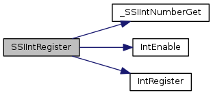
| void SSIIntRegister | ( | uint32_t | ui32Base, |
| void(*)(void) | pfnHandler | ||
| ) |
Registers an interrupt handler for the synchronous serial interface.
| ui32Base | specifies the SSI module base address. |
| pfnHandler | is a pointer to the function to be called when the synchronous serial interface interrupt occurs. |
This function registers the handler to be called when an SSI interrupt occurs. This function enables the global interrupt in the interrupt controller; specific SSI interrupts must be enabled via SSIIntEnable(). If necessary, it is the interrupt handler's responsibility to clear the interrupt source via SSIIntClear().
Definition at line 353 of file ssi.c.
References _SSIIntNumberGet(), ASSERT, IntEnable(), and IntRegister().
| uint32_t SSIIntStatus | ( | uint32_t | ui32Base, |
| bool | bMasked | ||
| ) |
Gets the current interrupt status.
| ui32Base | specifies the SSI module base address. |
| bMasked | is false if the raw interrupt status is required or true if the masked interrupt status is required. |
This function returns the interrupt status for the SSI module. Either the raw interrupt status or the status of interrupts that are allowed to reflect to the processor can be returned.
Definition at line 499 of file ssi.c.
References ASSERT, HWREG, SSI_O_MIS, and SSI_O_RIS.
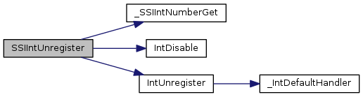
| void SSIIntUnregister | ( | uint32_t | ui32Base | ) |
Unregisters an interrupt handler for the synchronous serial interface.
| ui32Base | specifies the SSI module base address. |
This function clears the handler to be called when an SSI interrupt occurs. This function also masks off the interrupt in the interrupt controller so that the interrupt handler no longer is called.
Definition at line 397 of file ssi.c.
References _SSIIntNumberGet(), ASSERT, IntDisable(), and IntUnregister().
|
static |
Definition at line 63 of file ssi.c.
Referenced by _SSIIntNumberGet().
|
static |
Definition at line 73 of file ssi.c.
Referenced by _SSIIntNumberGet().
|
static |
|
static |
 1.8.9.1
