|
EE445M RTOS
Taken at the University of Texas Spring 2015
|
|
EE445M RTOS
Taken at the University of Texas Spring 2015
|
Macros | |
| #define | NEW_TIMER_CONFIGURATION CLASS_IS_TM4C129 |
Functions | |
| static uint32_t | _TimerIntNumberGet (uint32_t ui32Base, uint32_t ui32Timer) |
| void | TimerEnable (uint32_t ui32Base, uint32_t ui32Timer) |
| void | TimerDisable (uint32_t ui32Base, uint32_t ui32Timer) |
| void | TimerConfigure (uint32_t ui32Base, uint32_t ui32Config) |
| void | TimerControlLevel (uint32_t ui32Base, uint32_t ui32Timer, bool bInvert) |
| void | TimerControlTrigger (uint32_t ui32Base, uint32_t ui32Timer, bool bEnable) |
| void | TimerControlEvent (uint32_t ui32Base, uint32_t ui32Timer, uint32_t ui32Event) |
| void | TimerControlStall (uint32_t ui32Base, uint32_t ui32Timer, bool bStall) |
| void | TimerControlWaitOnTrigger (uint32_t ui32Base, uint32_t ui32Timer, bool bWait) |
| void | TimerRTCEnable (uint32_t ui32Base) |
| void | TimerRTCDisable (uint32_t ui32Base) |
| void | TimerClockSourceSet (uint32_t ui32Base, uint32_t ui32Source) |
| uint32_t | TimerClockSourceGet (uint32_t ui32Base) |
| void | TimerPrescaleSet (uint32_t ui32Base, uint32_t ui32Timer, uint32_t ui32Value) |
| uint32_t | TimerPrescaleGet (uint32_t ui32Base, uint32_t ui32Timer) |
| void | TimerPrescaleMatchSet (uint32_t ui32Base, uint32_t ui32Timer, uint32_t ui32Value) |
| uint32_t | TimerPrescaleMatchGet (uint32_t ui32Base, uint32_t ui32Timer) |
| void | TimerLoadSet (uint32_t ui32Base, uint32_t ui32Timer, uint32_t ui32Value) |
| uint32_t | TimerLoadGet (uint32_t ui32Base, uint32_t ui32Timer) |
| void | TimerLoadSet64 (uint32_t ui32Base, uint64_t ui64Value) |
| uint64_t | TimerLoadGet64 (uint32_t ui32Base) |
| uint32_t | TimerValueGet (uint32_t ui32Base, uint32_t ui32Timer) |
| uint64_t | TimerValueGet64 (uint32_t ui32Base) |
| void | TimerMatchSet (uint32_t ui32Base, uint32_t ui32Timer, uint32_t ui32Value) |
| uint32_t | TimerMatchGet (uint32_t ui32Base, uint32_t ui32Timer) |
| void | TimerMatchSet64 (uint32_t ui32Base, uint64_t ui64Value) |
| uint64_t | TimerMatchGet64 (uint32_t ui32Base) |
| void | TimerIntRegister (uint32_t ui32Base, uint32_t ui32Timer, void(*pfnHandler)(void)) |
| void | TimerIntUnregister (uint32_t ui32Base, uint32_t ui32Timer) |
| void | TimerIntEnable (uint32_t ui32Base, uint32_t ui32IntFlags) |
| void | TimerIntDisable (uint32_t ui32Base, uint32_t ui32IntFlags) |
| uint32_t | TimerIntStatus (uint32_t ui32Base, bool bMasked) |
| void | TimerIntClear (uint32_t ui32Base, uint32_t ui32IntFlags) |
| void | TimerSynchronize (uint32_t ui32Base, uint32_t ui32Timers) |
| void | TimerADCEventSet (uint32_t ui32Base, uint32_t ui32ADCEvent) |
| uint32_t | TimerADCEventGet (uint32_t ui32Base) |
| void | TimerDMAEventSet (uint32_t ui32Base, uint32_t ui32DMAEvent) |
| uint32_t | TimerDMAEventGet (uint32_t ui32Base) |
| void | TimerUpdateMode (uint32_t ui32Base, uint32_t ui32Timer, uint32_t ui32Config) |
Variables | |
| static const uint32_t | g_ppui32TimerIntMap [][2] |
| static const uint_fast8_t | g_ui8TimerIntMapRows |
| static const uint32_t | g_ppui32TimerIntMapSnowflake [][2] |
| static const uint_fast8_t | g_ui8TimerIntMapRowsSnowflake |
| #define NEW_TIMER_CONFIGURATION CLASS_IS_TM4C129 |
Definition at line 64 of file timer.c.
Referenced by TimerConfigure(), and TimerControlTrigger().
|
static |
Returns a timer modules interrupt number.
| ui32Base | is the base address of the selected timer. |
| ui32Timer | specifies the timer(s) to enable; must be one of TIMER_A, TIMER_B, or TIMER_BOTH. |
This function returns the interrupt number for a given timer module specified by the ui32Base and ui32Timer parameter.
Definition at line 146 of file timer.c.
References CLASS_IS_TM4C129, g_ppui32TimerIntMap, g_ppui32TimerIntMapSnowflake, g_ui8TimerIntMapRows, g_ui8TimerIntMapRowsSnowflake, and TIMER_B.
Referenced by TimerIntRegister(), and TimerIntUnregister().

| uint32_t TimerADCEventGet | ( | uint32_t | ui32Base | ) |
Returns the events that can cause an ADC trigger event.
| ui32Base | is the base address of the timer module. |
This function returns the timer events that can cause an ADC trigger event. The ADC trigger events are the logical OR of any of the following values:
Definition at line 1724 of file timer.c.
References ASSERT, HWREG, and TIMER_O_ADCEV.
| void TimerADCEventSet | ( | uint32_t | ui32Base, |
| uint32_t | ui32ADCEvent | ||
| ) |
Enables the events that can cause an ADC trigger event.
| ui32Base | is the base address of the timer module. |
| ui32ADCEvent | is a bit mask of the events that can cause an ADC trigger event. |
This function enables the timer events that can cause an ADC trigger event. The ADC trigger events are specified in the ui32ADCEvent parameter by passing in the logical OR of any of the following values:
Definition at line 1678 of file timer.c.
References ASSERT, HWREG, and TIMER_O_ADCEV.
| uint32_t TimerClockSourceGet | ( | uint32_t | ui32Base | ) |
Returns the clock source for the specified timer module.
| ui32Base | is the base address of the timer module. |
This function returns the clock source for the specified timer module. The possible clock sources are the system clock (TIMER_CLOCK_SYSTEM) or the precision internal oscillator (TIMER_CLOCK_PIOSC).
Definition at line 752 of file timer.c.
References ASSERT, HWREG, and TIMER_O_CC.
| void TimerClockSourceSet | ( | uint32_t | ui32Base, |
| uint32_t | ui32Source | ||
| ) |
Sets the clock source for the specified timer module.
| ui32Base | is the base address of the timer module. |
| ui32Source | is the clock source for the timer module. |
This function sets the clock source for both timer A and timer B for the given timer module. The possible clock sources are the system clock (TIMER_CLOCK_SYSTEM) or the precision internal oscillator (TIMER_CLOCK_PIOSC).
Definition at line 719 of file timer.c.
References ASSERT, HWREG, TIMER_CLOCK_PIOSC, TIMER_CLOCK_SYSTEM, and TIMER_O_CC.
| void TimerConfigure | ( | uint32_t | ui32Base, |
| uint32_t | ui32Config | ||
| ) |
Configures the timer(s).
| ui32Base | is the base address of the timer module. |
| ui32Config | is the configuration for the timer. |
This function configures the operating mode of the timer(s). The timer module is disabled before being configured and is left in the disabled state. The timer can be configured to be a single full-width timer by using the TIMER_CFG_* values or a pair of half-width timers using the TIMER_CFG_A_* and TIMER_CFG_B_* values passed in the ui32Config parameter.
The configuration is specified in ui32Config as one of the following values:
When configured for a pair of half-width timers, each timer is separately configured. The first timer is configured by setting ui32Config to the result of a logical OR operation between one of the following values and ui32Config:
Some Tiva devices also allow configuring an action when the timers reach their timeout. Please consult the data sheet for the part you are using to determine whether configuring actions on timers is available.
One of the following can be combined with the TIMER_CFG_* values to enable an action on timer A:
One of the following can be combined with the TIMER_CFG_* values to enable an action on timer B:
Similarly, the second timer is configured by setting ui32Config to the result of a logical OR operation between one of the corresponding TIMER_CFG_B_* values and ui32Config.
Definition at line 347 of file timer.c.
References ASSERT, HWREG, NEW_TIMER_CONFIGURATION, TIMER_CFG_A_CAP_COUNT, TIMER_CFG_A_CAP_TIME, TIMER_CFG_A_ONE_SHOT, TIMER_CFG_A_ONE_SHOT_UP, TIMER_CFG_A_PERIODIC, TIMER_CFG_A_PERIODIC_UP, TIMER_CFG_A_PWM, TIMER_CFG_B_CAP_COUNT, TIMER_CFG_B_CAP_COUNT_UP, TIMER_CFG_B_CAP_TIME, TIMER_CFG_B_CAP_TIME_UP, TIMER_CFG_B_ONE_SHOT, TIMER_CFG_B_ONE_SHOT_UP, TIMER_CFG_B_PERIODIC, TIMER_CFG_B_PERIODIC_UP, TIMER_CFG_B_PWM, TIMER_CFG_ONE_SHOT, TIMER_CFG_ONE_SHOT_UP, TIMER_CFG_PERIODIC, TIMER_CFG_PERIODIC_UP, TIMER_CFG_RTC, TIMER_CFG_SPLIT_PAIR, TIMER_CTL_TAEN, TIMER_CTL_TBEN, TIMER_O_CFG, TIMER_O_CTL, TIMER_O_TAMR, TIMER_O_TBMR, TIMER_TAMR_TAPWMIE, and TIMER_TBMR_TBPWMIE.
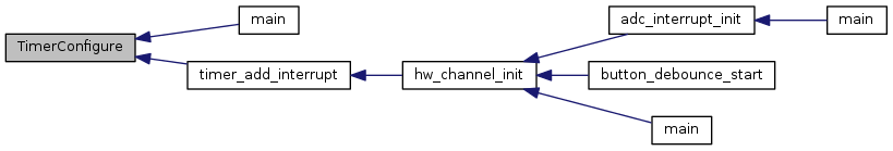
Referenced by main(), and timer_add_interrupt().
| void TimerControlEvent | ( | uint32_t | ui32Base, |
| uint32_t | ui32Timer, | ||
| uint32_t | ui32Event | ||
| ) |
Controls the event type.
| ui32Base | is the base address of the timer module. |
| ui32Timer | specifies the timer(s) to be adjusted; must be one of TIMER_A, TIMER_B, or TIMER_BOTH. |
| ui32Event | specifies the type of event; must be one of TIMER_EVENT_POS_EDGE, TIMER_EVENT_NEG_EDGE, or TIMER_EVENT_BOTH_EDGES. |
This function configures the signal edge(s) that triggers the timer when in capture mode.
Definition at line 529 of file timer.c.
References ASSERT, HWREG, TIMER_A, TIMER_B, TIMER_BOTH, TIMER_CTL_TAEVENT_M, TIMER_CTL_TBEVENT_M, and TIMER_O_CTL.
| void TimerControlLevel | ( | uint32_t | ui32Base, |
| uint32_t | ui32Timer, | ||
| bool | bInvert | ||
| ) |
Controls the output level.
| ui32Base | is the base address of the timer module. |
| ui32Timer | specifies the timer(s) to adjust; must be one of TIMER_A, TIMER_B, or TIMER_BOTH. |
| bInvert | specifies the output level. |
This function configures the PWM output level for the specified timer. If the bInvert parameter is true, then the timer's output is made active low; otherwise, it is made active high.
Definition at line 427 of file timer.c.
References ASSERT, HWREG, TIMER_A, TIMER_B, TIMER_BOTH, TIMER_CTL_TAPWML, TIMER_CTL_TBPWML, and TIMER_O_CTL.
| void TimerControlStall | ( | uint32_t | ui32Base, |
| uint32_t | ui32Timer, | ||
| bool | bStall | ||
| ) |
Controls the stall handling.
| ui32Base | is the base address of the timer module. |
| ui32Timer | specifies the timer(s) to be adjusted; must be one of TIMER_A, TIMER_B, or TIMER_BOTH. |
| bStall | specifies the response to a stall signal. |
This function controls the stall response for the specified timer. If the bStall parameter is true, then the timer stops counting if the processor enters debug mode; otherwise the timer keeps running while in debug mode.
Definition at line 565 of file timer.c.
References ASSERT, HWREG, TIMER_A, TIMER_B, TIMER_BOTH, TIMER_CTL_TASTALL, TIMER_CTL_TBSTALL, and TIMER_O_CTL.
| void TimerControlTrigger | ( | uint32_t | ui32Base, |
| uint32_t | ui32Timer, | ||
| bool | bEnable | ||
| ) |
Enables or disables the ADC trigger output.
| ui32Base | is the base address of the timer module. |
| ui32Timer | specifies the timer to adjust; must be one of TIMER_A, TIMER_B, or TIMER_BOTH. |
| bEnable | specifies the desired ADC trigger state. |
This function controls the ADC trigger output for the specified timer. If the bEnable parameter is true, then the timer's ADC output trigger is enabled; otherwise it is disabled.
Definition at line 464 of file timer.c.
References ASSERT, HWREG, NEW_TIMER_CONFIGURATION, TIMER_A, TIMER_ADCEV_TATOADCEN, TIMER_ADCEV_TBTOADCEN, TIMER_B, TIMER_BOTH, TIMER_CTL_TAOTE, TIMER_CTL_TBOTE, TIMER_O_ADCEV, and TIMER_O_CTL.
Referenced by adc_interrupt_init().

| void TimerControlWaitOnTrigger | ( | uint32_t | ui32Base, |
| uint32_t | ui32Timer, | ||
| bool | bWait | ||
| ) |
Controls the wait on trigger handling.
| ui32Base | is the base address of the timer module. |
| ui32Timer | specifies the timer(s) to be adjusted; must be one of TIMER_A, TIMER_B, or TIMER_BOTH. |
| bWait | specifies if the timer should wait for a trigger input. |
This function controls whether or not a timer waits for a trigger input to start counting. When enabled, the previous timer in the trigger chain must count to its timeout in order for this timer to start counting. Refer to the part's data sheet for a description of the trigger chain.
Definition at line 607 of file timer.c.
References ASSERT, HWREG, TIMER_A, TIMER_B, TIMER_BOTH, TIMER_O_TAMR, TIMER_O_TBMR, TIMER_TAMR_TAWOT, and TIMER_TBMR_TBWOT.
| void TimerDisable | ( | uint32_t | ui32Base, |
| uint32_t | ui32Timer | ||
| ) |
Disables the timer(s).
| ui32Base | is the base address of the timer module. |
| ui32Timer | specifies the timer(s) to disable; must be one of TIMER_A, TIMER_B, or TIMER_BOTH. |
This function disables operation of the timer module.
Definition at line 240 of file timer.c.
References ASSERT, HWREG, TIMER_A, TIMER_B, TIMER_BOTH, TIMER_CTL_TAEN, TIMER_CTL_TBEN, and TIMER_O_CTL.
| uint32_t TimerDMAEventGet | ( | uint32_t | ui32Base | ) |
Returns the events that can trigger a uDMA request.
| ui32Base | is the base address of the timer module. |
This function returns the timer events that can trigger the start of a uDMA sequence. The uDMA trigger events are the logical OR of the following values:
Definition at line 1819 of file timer.c.
References ASSERT, HWREG, and TIMER_O_DMAEV.
| void TimerDMAEventSet | ( | uint32_t | ui32Base, |
| uint32_t | ui32DMAEvent | ||
| ) |
Enables the events that can trigger a uDMA request.
| ui32Base | is the base address of the timer module. |
| ui32DMAEvent | is a bit mask of the events that can trigger uDMA. |
This function enables the timer events that can trigger the start of a uDMA sequence. The uDMA trigger events are specified in the ui32DMAEvent parameter by passing in the logical OR of the following values:
Definition at line 1772 of file timer.c.
References ASSERT, HWREG, and TIMER_O_DMAEV.
| void TimerEnable | ( | uint32_t | ui32Base, |
| uint32_t | ui32Timer | ||
| ) |
Enables the timer(s).
| ui32Base | is the base address of the timer module. |
| ui32Timer | specifies the timer(s) to enable; must be one of TIMER_A, TIMER_B, or TIMER_BOTH. |
This function enables operation of the timer module. The timer must be configured before it is enabled.
Definition at line 210 of file timer.c.
References ASSERT, HWREG, TIMER_A, TIMER_B, TIMER_BOTH, TIMER_CTL_TAEN, TIMER_CTL_TBEN, and TIMER_O_CTL.
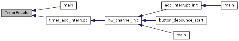
Referenced by main(), and timer_add_interrupt().
| void TimerIntClear | ( | uint32_t | ui32Base, |
| uint32_t | ui32IntFlags | ||
| ) |
Clears timer interrupt sources.
| ui32Base | is the base address of the timer module. |
| ui32IntFlags | is a bit mask of the interrupt sources to be cleared. |
The specified timer interrupt sources are cleared, so that they no longer assert. This function must be called in the interrupt handler to keep the interrupt from being triggered again immediately upon exit.
The ui32IntFlags parameter has the same definition as the ui32IntFlags parameter to TimerIntEnable().
Definition at line 1568 of file timer.c.
References ASSERT, HWREG, and TIMER_O_ICR.
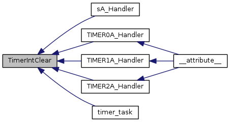
Referenced by sA_Handler(), TIMER0A_Handler(), TIMER1A_Handler(), TIMER2A_Handler(), and timer_task().
| void TimerIntDisable | ( | uint32_t | ui32Base, |
| uint32_t | ui32IntFlags | ||
| ) |
Disables individual timer interrupt sources.
| ui32Base | is the base address of the timer module. |
| ui32IntFlags | is the bit mask of the interrupt sources to be disabled. |
This function disables the indicated timer interrupt sources. Only the sources that are enabled can be reflected to the processor interrupt; disabled sources have no effect on the processor.
The ui32IntFlags parameter has the same definition as the ui32IntFlags parameter to TimerIntEnable().
Definition at line 1496 of file timer.c.
References ASSERT, HWREG, and TIMER_O_IMR.
| void TimerIntEnable | ( | uint32_t | ui32Base, |
| uint32_t | ui32IntFlags | ||
| ) |
Enables individual timer interrupt sources.
| ui32Base | is the base address of the timer module. |
| ui32IntFlags | is the bit mask of the interrupt sources to be enabled. |
This function enables the indicated timer interrupt sources. Only the sources that are enabled can be reflected to the processor interrupt; disabled sources have no effect on the processor.
The ui32IntFlags parameter must be the logical OR of any combination of the following:
Definition at line 1464 of file timer.c.
References ASSERT, HWREG, and TIMER_O_IMR.
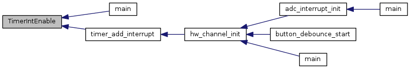
Referenced by main(), and timer_add_interrupt().
| void TimerIntRegister | ( | uint32_t | ui32Base, |
| uint32_t | ui32Timer, | ||
| void(*)(void) | pfnHandler | ||
| ) |
Registers an interrupt handler for the timer interrupt.
| ui32Base | is the base address of the timer module. |
| ui32Timer | specifies the timer(s); must be one of TIMER_A, TIMER_B, or TIMER_BOTH. |
| pfnHandler | is a pointer to the function to be called when the timer interrupt occurs. |
This function registers the handler to be called when a timer interrupt occurs. In addition, this function enables the global interrupt in the interrupt controller; specific timer interrupts must be enabled via TimerIntEnable(). It is the interrupt handler's responsibility to clear the interrupt source via TimerIntClear().
Definition at line 1360 of file timer.c.
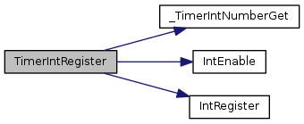
References _TimerIntNumberGet(), ASSERT, IntEnable(), IntRegister(), TIMER_A, TIMER_B, and TIMER_BOTH.
| uint32_t TimerIntStatus | ( | uint32_t | ui32Base, |
| bool | bMasked | ||
| ) |
Gets the current interrupt status.
| ui32Base | is the base address of the timer module. |
| bMasked | is false if the raw interrupt status is required and true if the masked interrupt status is required. |
This function returns the interrupt status for the timer module. Either the raw interrupt status or the status of interrupts that are allowed to reflect to the processor can be returned.
Definition at line 1526 of file timer.c.
References ASSERT, HWREG, TIMER_O_MIS, and TIMER_O_RIS.
| void TimerIntUnregister | ( | uint32_t | ui32Base, |
| uint32_t | ui32Timer | ||
| ) |
Unregisters an interrupt handler for the timer interrupt.
| ui32Base | is the base address of the timer module. |
| ui32Timer | specifies the timer(s); must be one of TIMER_A, TIMER_B, or TIMER_BOTH. |
This function unregisters the handler to be called when a timer interrupt occurs. This function also masks off the interrupt in the interrupt controller so that the interrupt handler is no longer called.
Definition at line 1409 of file timer.c.
References _TimerIntNumberGet(), ASSERT, IntDisable(), IntUnregister(), TIMER_A, TIMER_B, and TIMER_BOTH.

| uint32_t TimerLoadGet | ( | uint32_t | ui32Base, |
| uint32_t | ui32Timer | ||
| ) |
Gets the timer load value.
| ui32Base | is the base address of the timer module. |
| ui32Timer | specifies the timer; must be one of TIMER_A or TIMER_B. Only TIMER_A should be used when the timer is configured for full-width operation. |
This function gets the currently programmed interval load value for the specified timer.
Definition at line 1015 of file timer.c.
References ASSERT, HWREG, TIMER_A, TIMER_B, TIMER_O_TAILR, and TIMER_O_TBILR.
| uint64_t TimerLoadGet64 | ( | uint32_t | ui32Base | ) |
Gets the timer load value for a 64-bit timer.
| ui32Base | is the base address of the timer module. |
This function gets the currently programmed interval load value for the specified 64-bit timer.
Definition at line 1073 of file timer.c.
References ASSERT, HWREG, TIMER_O_TAILR, and TIMER_O_TBILR.
| void TimerLoadSet | ( | uint32_t | ui32Base, |
| uint32_t | ui32Timer, | ||
| uint32_t | ui32Value | ||
| ) |
Sets the timer load value.
| ui32Base | is the base address of the timer module. |
| ui32Timer | specifies the timer(s) to adjust; must be one of TIMER_A, TIMER_B, or TIMER_BOTH. Only TIMER_A should be used when the timer is configured for full-width operation. |
| ui32Value | is the load value. |
This function configures the timer load value; if the timer is running then the value is immediately loaded into the timer.
Definition at line 969 of file timer.c.
References ASSERT, HWREG, TIMER_A, TIMER_B, TIMER_BOTH, TIMER_O_TAILR, and TIMER_O_TBILR.
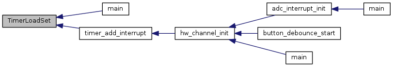
Referenced by main(), and timer_add_interrupt().
| void TimerLoadSet64 | ( | uint32_t | ui32Base, |
| uint64_t | ui64Value | ||
| ) |
Sets the timer load value for a 64-bit timer.
| ui32Base | is the base address of the timer module. |
| ui64Value | is the load value. |
This function configures the timer load value for a 64-bit timer; if the timer is running, then the value is immediately loaded into the timer.
Definition at line 1044 of file timer.c.
References ASSERT, HWREG, TIMER_O_TAILR, and TIMER_O_TBILR.
| uint32_t TimerMatchGet | ( | uint32_t | ui32Base, |
| uint32_t | ui32Timer | ||
| ) |
Gets the timer match value.
| ui32Base | is the base address of the timer module. |
| ui32Timer | specifies the timer; must be one of TIMER_A or TIMER_B. Only TIMER_A should be used when the timer is configured for full-width operation. |
This function gets the match value for the specified timer.
Definition at line 1249 of file timer.c.
References ASSERT, HWREG, TIMER_A, TIMER_B, TIMER_O_TAMATCHR, and TIMER_O_TBMATCHR.
| uint64_t TimerMatchGet64 | ( | uint32_t | ui32Base | ) |
Gets the timer match value for a 64-bit timer.
| ui32Base | is the base address of the timer module. |
This function gets the match value for the specified timer.
Definition at line 1307 of file timer.c.
References ASSERT, HWREG, TIMER_O_TAMATCHR, and TIMER_O_TBMATCHR.
| void TimerMatchSet | ( | uint32_t | ui32Base, |
| uint32_t | ui32Timer, | ||
| uint32_t | ui32Value | ||
| ) |
Sets the timer match value.
| ui32Base | is the base address of the timer module. |
| ui32Timer | specifies the timer(s) to adjust; must be one of TIMER_A, TIMER_B, or TIMER_BOTH. Only TIMER_A should be used when the timer is configured for full-width operation. |
| ui32Value | is the match value. |
This function configures the match value for a timer. This value is used in capture count mode to determine when to interrupt the processor and in PWM mode to determine the duty cycle of the output signal. On some Tiva devices, match interrupts can also be generated in periodic and one-shot modes.
Definition at line 1203 of file timer.c.
References ASSERT, HWREG, TIMER_A, TIMER_B, TIMER_BOTH, TIMER_O_TAMATCHR, and TIMER_O_TBMATCHR.
| void TimerMatchSet64 | ( | uint32_t | ui32Base, |
| uint64_t | ui64Value | ||
| ) |
Sets the timer match value for a 64-bit timer.
| ui32Base | is the base address of the timer module. |
| ui64Value | is the match value. |
This function configures the match value for a timer. This value is used in capture count mode to determine when to interrupt the processor and in PWM mode to determine the duty cycle of the output signal.
Definition at line 1279 of file timer.c.
References ASSERT, HWREG, TIMER_O_TAMATCHR, and TIMER_O_TBMATCHR.
| uint32_t TimerPrescaleGet | ( | uint32_t | ui32Base, |
| uint32_t | ui32Timer | ||
| ) |
Gets the timer prescale value.
| ui32Base | is the base address of the timer module. |
| ui32Timer | specifies the timer; must be one of TIMER_A or TIMER_B. |
This function gets the value of the input clock prescaler. The prescaler is only operational when in half-width mode and is used to extend the range of the half-width timer modes. The prescaler provides the least significant bits when counting down in periodic and one-shot modes; in all other modes, the prescaler provides the most significant bits.
Definition at line 839 of file timer.c.
References ASSERT, HWREG, TIMER_A, TIMER_B, TIMER_BOTH, TIMER_O_TAPR, and TIMER_O_TBPR.
| uint32_t TimerPrescaleMatchGet | ( | uint32_t | ui32Base, |
| uint32_t | ui32Timer | ||
| ) |
Gets the timer prescale match value.
| ui32Base | is the base address of the timer module. |
| ui32Timer | specifies the timer; must be one of TIMER_A or TIMER_B. |
This function gets the value of the input clock prescaler match value. When in a half-width mode that uses the counter match and prescaler, the prescale match effectively extends the range of the match. The prescaler provides the least significant bits when counting down in periodic and one-shot modes; in all other modes, the prescaler provides the most significant bits.
Definition at line 932 of file timer.c.
References ASSERT, HWREG, TIMER_A, TIMER_B, TIMER_BOTH, TIMER_O_TAPMR, and TIMER_O_TBPMR.
| void TimerPrescaleMatchSet | ( | uint32_t | ui32Base, |
| uint32_t | ui32Timer, | ||
| uint32_t | ui32Value | ||
| ) |
Sets the timer prescale match value.
| ui32Base | is the base address of the timer module. |
| ui32Timer | specifies the timer(s) to adjust; must be one of TIMER_A, TIMER_B, or TIMER_BOTH. |
| ui32Value | is the timer prescale match value which must be between 0 and 255 (inclusive) for 16/32-bit timers and between 0 and 65535 (inclusive) for 32/64-bit timers. |
This function configures the value of the input clock prescaler match value. When in a half-width mode that uses the counter match and the prescaler, the prescale match effectively extends the range of the match. The prescaler provides the least significant bits when counting down in periodic and one-shot modes; in all other modes, the prescaler provides the most significant bits.
Definition at line 881 of file timer.c.
References ASSERT, HWREG, TIMER_A, TIMER_B, TIMER_BOTH, TIMER_O_TAPMR, and TIMER_O_TBPMR.
| void TimerPrescaleSet | ( | uint32_t | ui32Base, |
| uint32_t | ui32Timer, | ||
| uint32_t | ui32Value | ||
| ) |
Sets the timer prescale value.
| ui32Base | is the base address of the timer module. |
| ui32Timer | specifies the timer(s) to adjust; must be one of TIMER_A, TIMER_B, or TIMER_BOTH. |
| ui32Value | is the timer prescale value which must be between 0 and 255 (inclusive) for 16/32-bit timers and between 0 and 65535 (inclusive) for 32/64-bit timers. |
This function configures the value of the input clock prescaler. The prescaler is only operational when in half-width mode and is used to extend the range of the half-width timer modes. The prescaler provides the least significant bits when counting down in periodic and one-shot modes; in all other modes, the prescaler provides the most significant bits.
Definition at line 790 of file timer.c.
References ASSERT, HWREG, TIMER_A, TIMER_B, TIMER_BOTH, TIMER_O_TAPR, and TIMER_O_TBPR.
| void TimerRTCDisable | ( | uint32_t | ui32Base | ) |
Disables RTC counting.
| ui32Base | is the base address of the timer module. |
This function causes the timer to stop counting when in RTC mode.
Definition at line 686 of file timer.c.
References ASSERT, HWREG, TIMER_CTL_RTCEN, and TIMER_O_CTL.
| void TimerRTCEnable | ( | uint32_t | ui32Base | ) |
Enables RTC counting.
| ui32Base | is the base address of the timer module. |
This function causes the timer to start counting when in RTC mode. If not configured for RTC mode, this function does nothing.
Definition at line 661 of file timer.c.
References ASSERT, HWREG, TIMER_CTL_RTCEN, and TIMER_O_CTL.
| void TimerSynchronize | ( | uint32_t | ui32Base, |
| uint32_t | ui32Timers | ||
| ) |
Synchronizes the counters in a set of timers.
| ui32Base | is the base address of the timer module. This parameter must be the base address of Timer0 (in other words, TIMER0_BASE). |
| ui32Timers | is the set of timers to synchronize. |
This function synchronizes the counters in a specified set of timers. When a timer is running in half-width mode, each half can be included or excluded in the synchronization event. When a timer is running in full-width mode, only the A timer can be synchronized (specifying the B timer has no effect).
The ui32Timers parameter is the logical OR of any of the following defines:
Definition at line 1629 of file timer.c.
References ASSERT, HWREG, TIMER0_BASE, and TIMER_O_SYNC.
| void TimerUpdateMode | ( | uint32_t | ui32Base, |
| uint32_t | ui32Timer, | ||
| uint32_t | ui32Config | ||
| ) |
This function configures the update of timer load and match settings.
| ui32Base | is the base address of the timer module. |
| ui32Timer | specifies the timer(s); must be one of TIMER_A, TIMER_B, or TIMER_BOTH. |
| ui32Config | is a combination of the updates methods for the timers specified in the ui32Timer parameter. |
This function configures how the timer updates the timer load and match values for the timers. The ui32Timer values can be TIMER_A, TIMER_B, or TIMER_BOTH to apply the settings in ui32Config to either timer or both timers. If the timer is not split then the TIMER_A should be used. The ui32Config values affects when the TimerLoadSet() and TimerLoadSet64() values take effect.
Similarly the ui32Config value affects when the TimerMatchSet() and TimerMatchSet64() values take effect.
Definition at line 1871 of file timer.c.
References HWREG, TIMER_A, TIMER_B, TIMER_O_TAMR, and TIMER_O_TBMR.
| uint32_t TimerValueGet | ( | uint32_t | ui32Base, |
| uint32_t | ui32Timer | ||
| ) |
Gets the current timer value.
| ui32Base | is the base address of the timer module. |
| ui32Timer | specifies the timer; must be one of TIMER_A or TIMER_B. Only TIMER_A should be used when the timer is configured for full-width operation. |
This function reads the current value of the specified timer.
Definition at line 1122 of file timer.c.
References ASSERT, HWREG, TIMER_A, TIMER_B, TIMER_O_TAR, and TIMER_O_TBR.
| uint64_t TimerValueGet64 | ( | uint32_t | ui32Base | ) |
Gets the current 64-bit timer value.
| ui32Base | is the base address of the timer module. |
This function reads the current value of the specified timer.
Definition at line 1149 of file timer.c.
References ASSERT, HWREG, TIMER_O_TAR, and TIMER_O_TBR.
|
static |
|
static |
|
static |
|
static |
Definition at line 100 of file timer.c.
Referenced by _TimerIntNumberGet().
 1.8.9.1
