|
EE445M RTOS
Taken at the University of Texas Spring 2015
|
|
EE445M RTOS
Taken at the University of Texas Spring 2015
|
Macros | |
| #define | USB_INTEP_RX_SHIFT 16 |
| #define | USB_RX_EPSTATUS_SHIFT 16 |
| #define | EP_OFFSET(Endpoint) (Endpoint - 0x10) |
Functions | |
| static void | _USBIndexWrite (uint32_t ui32Base, uint32_t ui32Endpoint, uint32_t ui32IndexedReg, uint32_t ui32Value, uint32_t ui32Size) |
| static uint32_t | _USBIndexRead (uint32_t ui32Base, uint32_t ui32Endpoint, uint32_t ui32IndexedReg, uint32_t ui32Size) |
| void | USBHostSuspend (uint32_t ui32Base) |
| void | USBHostReset (uint32_t ui32Base, bool bStart) |
| void | USBHighSpeed (uint32_t ui32Base, bool bEnable) |
| void | USBHostResume (uint32_t ui32Base, bool bStart) |
| uint32_t | USBHostSpeedGet (uint32_t ui32Base) |
| uint32_t | USBDevSpeedGet (uint32_t ui32Base) |
| void | USBIntDisableControl (uint32_t ui32Base, uint32_t ui32Flags) |
| void | USBIntEnableControl (uint32_t ui32Base, uint32_t ui32Flags) |
| uint32_t | USBIntStatusControl (uint32_t ui32Base) |
| void | USBIntDisableEndpoint (uint32_t ui32Base, uint32_t ui32Flags) |
| void | USBIntEnableEndpoint (uint32_t ui32Base, uint32_t ui32Flags) |
| uint32_t | USBIntStatusEndpoint (uint32_t ui32Base) |
| static uint32_t | _USBIntNumberGet (uint32_t ui32Base) |
| void | USBIntRegister (uint32_t ui32Base, void(*pfnHandler)(void)) |
| void | USBIntUnregister (uint32_t ui32Base) |
| uint32_t | USBEndpointStatus (uint32_t ui32Base, uint32_t ui32Endpoint) |
| void | USBHostEndpointStatusClear (uint32_t ui32Base, uint32_t ui32Endpoint, uint32_t ui32Flags) |
| void | USBDevEndpointStatusClear (uint32_t ui32Base, uint32_t ui32Endpoint, uint32_t ui32Flags) |
| void | USBHostEndpointDataToggle (uint32_t ui32Base, uint32_t ui32Endpoint, bool bDataToggle, uint32_t ui32Flags) |
| void | USBEndpointDataToggleClear (uint32_t ui32Base, uint32_t ui32Endpoint, uint32_t ui32Flags) |
| void | USBHostEndpointPing (uint32_t ui32Base, uint32_t ui32Endpoint, bool bEnable) |
| void | USBDevEndpointStall (uint32_t ui32Base, uint32_t ui32Endpoint, uint32_t ui32Flags) |
| void | USBDevEndpointStallClear (uint32_t ui32Base, uint32_t ui32Endpoint, uint32_t ui32Flags) |
| void | USBDevConnect (uint32_t ui32Base) |
| void | USBDevDisconnect (uint32_t ui32Base) |
| void | USBDevAddrSet (uint32_t ui32Base, uint32_t ui32Address) |
| uint32_t | USBDevAddrGet (uint32_t ui32Base) |
| void | USBHostEndpointConfig (uint32_t ui32Base, uint32_t ui32Endpoint, uint32_t ui32MaxPayload, uint32_t ui32NAKPollInterval, uint32_t ui32TargetEndpoint, uint32_t ui32Flags) |
| void | USBHostEndpointSpeed (uint32_t ui32Base, uint32_t ui32Endpoint, uint32_t ui32Flags) |
| void | USBDevEndpointConfigSet (uint32_t ui32Base, uint32_t ui32Endpoint, uint32_t ui32MaxPacketSize, uint32_t ui32Flags) |
| void | USBDevEndpointConfigGet (uint32_t ui32Base, uint32_t ui32Endpoint, uint32_t *pui32MaxPacketSize, uint32_t *pui32Flags) |
| void | USBFIFOConfigSet (uint32_t ui32Base, uint32_t ui32Endpoint, uint32_t ui32FIFOAddress, uint32_t ui32FIFOSize, uint32_t ui32Flags) |
| void | USBFIFOConfigGet (uint32_t ui32Base, uint32_t ui32Endpoint, uint32_t *pui32FIFOAddress, uint32_t *pui32FIFOSize, uint32_t ui32Flags) |
| void | USBEndpointDMAConfigSet (uint32_t ui32Base, uint32_t ui32Endpoint, uint32_t ui32Config) |
| void | USBEndpointDMAEnable (uint32_t ui32Base, uint32_t ui32Endpoint, uint32_t ui32Flags) |
| void | USBEndpointDMADisable (uint32_t ui32Base, uint32_t ui32Endpoint, uint32_t ui32Flags) |
| uint32_t | USBEndpointDataAvail (uint32_t ui32Base, uint32_t ui32Endpoint) |
| int32_t | USBEndpointDataGet (uint32_t ui32Base, uint32_t ui32Endpoint, uint8_t *pui8Data, uint32_t *pui32Size) |
| void | USBDevEndpointDataAck (uint32_t ui32Base, uint32_t ui32Endpoint, bool bIsLastPacket) |
| void | USBHostEndpointDataAck (uint32_t ui32Base, uint32_t ui32Endpoint) |
| int32_t | USBEndpointDataPut (uint32_t ui32Base, uint32_t ui32Endpoint, uint8_t *pui8Data, uint32_t ui32Size) |
| int32_t | USBEndpointDataSend (uint32_t ui32Base, uint32_t ui32Endpoint, uint32_t ui32TransType) |
| void | USBFIFOFlush (uint32_t ui32Base, uint32_t ui32Endpoint, uint32_t ui32Flags) |
| void | USBHostRequestIN (uint32_t ui32Base, uint32_t ui32Endpoint) |
| void | USBHostRequestINClear (uint32_t ui32Base, uint32_t ui32Endpoint) |
| void | USBHostRequestStatus (uint32_t ui32Base) |
| void | USBHostAddrSet (uint32_t ui32Base, uint32_t ui32Endpoint, uint32_t ui32Addr, uint32_t ui32Flags) |
| uint32_t | USBHostAddrGet (uint32_t ui32Base, uint32_t ui32Endpoint, uint32_t ui32Flags) |
| void | USBHostHubAddrSet (uint32_t ui32Base, uint32_t ui32Endpoint, uint32_t ui32Addr, uint32_t ui32Flags) |
| uint32_t | USBHostHubAddrGet (uint32_t ui32Base, uint32_t ui32Endpoint, uint32_t ui32Flags) |
| void | USBHostPwrConfig (uint32_t ui32Base, uint32_t ui32Flags) |
| void | USBHostPwrFaultEnable (uint32_t ui32Base) |
| void | USBHostPwrFaultDisable (uint32_t ui32Base) |
| void | USBHostPwrEnable (uint32_t ui32Base) |
| void | USBHostPwrDisable (uint32_t ui32Base) |
| uint32_t | USBFrameNumberGet (uint32_t ui32Base) |
| void | USBOTGSessionRequest (uint32_t ui32Base, bool bStart) |
| uint32_t | USBFIFOAddrGet (uint32_t ui32Base, uint32_t ui32Endpoint) |
| uint32_t | USBModeGet (uint32_t ui32Base) |
| void | USBEndpointDMAChannel (uint32_t ui32Base, uint32_t ui32Endpoint, uint32_t ui32Channel) |
| void | USBHostMode (uint32_t ui32Base) |
| void | USBDevMode (uint32_t ui32Base) |
| void | USBOTGMode (uint32_t ui32Base) |
| void | USBModeConfig (uint32_t ui32Base, uint32_t ui32Mode) |
| void | USBPHYPowerOff (uint32_t ui32Base) |
| void | USBPHYPowerOn (uint32_t ui32Base) |
| void | USBEndpointPacketCountSet (uint32_t ui32Base, uint32_t ui32Endpoint, uint32_t ui32Count) |
| uint32_t | USBNumEndpointsGet (uint32_t ui32Base) |
| uint32_t | USBControllerVersion (uint32_t ui32Base) |
| void | USBClockEnable (uint32_t ui32Base, uint32_t ui32Div, uint32_t ui32Flags) |
| void | USBClockDisable (uint32_t ui32Base) |
| #define EP_OFFSET | ( | Endpoint | ) | (Endpoint - 0x10) |
Definition at line 82 of file usb.c.
Referenced by USBDevEndpointConfigGet(), USBDevEndpointConfigSet(), USBDevEndpointDataAck(), USBDevEndpointStall(), USBDevEndpointStallClear(), USBDevEndpointStatusClear(), USBEndpointDataAvail(), USBEndpointDataGet(), USBEndpointDataToggleClear(), USBEndpointDMAConfigSet(), USBEndpointDMADisable(), USBEndpointDMAEnable(), USBEndpointStatus(), USBFIFOFlush(), USBHostEndpointConfig(), USBHostEndpointDataAck(), USBHostEndpointDataToggle(), USBHostEndpointSpeed(), USBHostEndpointStatusClear(), USBHostRequestIN(), and USBHostRequestINClear().
| #define USB_INTEP_RX_SHIFT 16 |
Definition at line 66 of file usb.c.
Referenced by USBIntDisableEndpoint(), USBIntEnableEndpoint(), and USBIntStatusEndpoint().
| #define USB_RX_EPSTATUS_SHIFT 16 |
Definition at line 74 of file usb.c.
Referenced by USBDevEndpointStatusClear(), USBEndpointStatus(), and USBHostEndpointStatusClear().
|
static |
Definition at line 164 of file usb.c.
References ASSERT, HWREGB, HWREGH, USB0_BASE, and USB_O_EPIDX.
Referenced by USBFIFOConfigGet().

|
static |
Definition at line 101 of file usb.c.
References ASSERT, HWREGB, HWREGH, USB0_BASE, and USB_O_EPIDX.
Referenced by USBFIFOConfigSet().

|
static |
Returns the interrupt number for a specified USB module.
| ui32Base | is the base address of the USB module. |
This function returns the interrupt number for the USB module with the base address passed in the ui32Base parameter.
Definition at line 818 of file usb.c.
References CLASS_IS_TM4C123, CLASS_IS_TM4C129, INT_USB0_TM4C123, and INT_USB0_TM4C129.
Referenced by USBIntRegister(), and USBIntUnregister().

| void USBClockDisable | ( | uint32_t | ui32Base | ) |
Disables the clocking of the USB controller's PHY.
| ui32Base | specifies the USB module base address. |
This function disables the USB PHY clock. This function should not be called in applications where the USB controller is used.
Example: Disable the USB PHY clock input.
//! //
//! // Disable clocking of the USB controller's PHY.
//! //
//! USBClockDisable(USB0_BASE);
//!
\note The ability to configure the USB PHY clock is not available on all
Tiva devices.  Please consult the data sheet for the Tiva device
that you are using to determine if this feature is available.

\return None.
Definition at line 4346 of file usb.c.
References ASSERT, HWREG, USB0_BASE, and USB_O_CC.
| void USBClockEnable | ( | uint32_t | ui32Base, |
| uint32_t | ui32Div, | ||
| uint32_t | ui32Flags | ||
| ) |
Configures and enables the clocking to the USB controller's PHY.
| ui32Base | specifies the USB module base address. |
| ui32Div | specifies the divider for the internal USB PHY clock. |
| ui32Flags | configures the internal USB PHY clock and specifies the clock source for a ULPI-connected PHY. |
This function configures and enables the USB PHY clock. In addition, for systems that use a ULPI-connected external PHY, this function configures the source for the PHY clock. The ui32Flags parameter specifies the clock source with the following values:
The ui32Div parameter is used to specify a divider for the internal clock if the USB_CLOCK_INTERNAL is specified and is ignored if USB_CLOCK_EXTERNAL is specified. When the USB_CLOCK_INTERNAL is specified, the ui32Div value must be set so that the PLL_VCO/ui32Div results in a 60-MHz clock.
Example: Enable the USB clock with a 480-MHz PLL setting.
//! //
//! // Enable the USB clock using a 480-MHz PLL.
//! // (480-MHz/8 = 60-MHz)
//! //
//! USBClockEnable(USB0_BASE, 8, USB_CLOCK_INTERNAL);
//!
\note The ability to configure the USB PHY clock is not available on
all Tiva devices.  Please consult the data sheet for the Tiva
device that you are using to determine if this feature is available.

\return None.
Definition at line 4310 of file usb.c.
References ASSERT, HWREG, USB0_BASE, and USB_O_CC.
| uint32_t USBControllerVersion | ( | uint32_t | ui32Base | ) |
Returns the version of the USB controller.
| ui32Base | specifies the USB module base address. |
This function returns the version number of the USB controller, which can be be used to adjust for slight differences between the USB controllers in the Tiva family. The values that are returned are USB_CONTROLLER_VER_0 and USB_CONTROLLER_VER_1.
Example: Get the version of the Tiva USB controller.
//! uint32_t ui32Version;
//!
//! //
//! // Retrieve the version of the Tiva USB controller.
//! //
//! ui32Version = USBControllerVersion(USB0_BASE);
//!
\return This function returns one of the \b USB_CONTROLLER_VER_ values.
Definition at line 4256 of file usb.c.
References HWREG, USB_O_PP, and USB_PP_TYPE_M.
| uint32_t USBDevAddrGet | ( | uint32_t | ui32Base | ) |
Returns the current device address in device mode.
| ui32Base | specifies the USB module base address. |
This function returns the current device address. This address was set by a call to USBDevAddrSet().
Definition at line 1585 of file usb.c.
References ASSERT, HWREGB, USB0_BASE, and USB_O_FADDR.
| void USBDevAddrSet | ( | uint32_t | ui32Base, |
| uint32_t | ui32Address | ||
| ) |
Sets the address in device mode.
| ui32Base | specifies the USB module base address. |
| ui32Address | is the address to use for a device. |
This function configures the device address on the USB bus. This address was likely received via a SET ADDRESS command from the host controller.
Definition at line 1557 of file usb.c.
References ASSERT, HWREGB, USB0_BASE, and USB_O_FADDR.
| void USBDevConnect | ( | uint32_t | ui32Base | ) |
Connects the USB controller to the bus in device mode.
| ui32Base | specifies the USB module base address. |
This function causes the soft connect feature of the USB controller to be enabled. Call USBDevDisconnect() to remove the USB device from the bus.
Definition at line 1499 of file usb.c.
References ASSERT, HWREGB, USB0_BASE, USB_O_POWER, and USB_POWER_SOFTCONN.
| void USBDevDisconnect | ( | uint32_t | ui32Base | ) |
Removes the USB controller from the bus in device mode.
| ui32Base | specifies the USB module base address. |
This function causes the soft connect feature of the USB controller to remove the device from the USB bus. A call to USBDevConnect() is needed to reconnect to the bus.
Definition at line 1528 of file usb.c.
References ASSERT, HWREGB, USB0_BASE, USB_O_POWER, and USB_POWER_SOFTCONN.
| void USBDevEndpointConfigGet | ( | uint32_t | ui32Base, |
| uint32_t | ui32Endpoint, | ||
| uint32_t * | pui32MaxPacketSize, | ||
| uint32_t * | pui32Flags | ||
| ) |
Gets the current configuration for an endpoint.
| ui32Base | specifies the USB module base address. |
| ui32Endpoint | is the endpoint to access. |
| pui32MaxPacketSize | is a pointer which is written with the maximum packet size for this endpoint. |
| pui32Flags | is a pointer which is written with the current endpoint settings. On entry to the function, this pointer must contain either USB_EP_DEV_IN or USB_EP_DEV_OUT to indicate whether the IN or OUT endpoint is to be queried. |
This function returns the basic configuration for an endpoint in device mode. The values returned in *pui32MaxPacketSize and *pui32Flags are equivalent to the ui32MaxPacketSize and ui32Flags previously passed to USBDevEndpointConfigSet() for this endpoint.
Definition at line 2213 of file usb.c.
References ASSERT, EP_OFFSET, HWREGB, HWREGH, USB0_BASE, USB_EP_1, USB_EP_2, USB_EP_3, USB_EP_4, USB_EP_5, USB_EP_6, USB_EP_7, USB_EP_AUTO_CLEAR, USB_EP_AUTO_SET, USB_EP_DEV_IN, USB_EP_DEV_OUT, USB_EP_DMA_MODE_0, USB_EP_DMA_MODE_1, USB_EP_MODE_BULK, USB_EP_MODE_ISOC, USB_O_RXCSRH1, USB_O_RXMAXP1, USB_O_TXCSRH1, USB_O_TXMAXP1, USB_RXCSRH1_AUTOCL, USB_RXCSRH1_DMAEN, USB_RXCSRH1_DMAMOD, USB_RXCSRH1_ISO, USB_TXCSRH1_AUTOSET, USB_TXCSRH1_DMAEN, USB_TXCSRH1_DMAMOD, and USB_TXCSRH1_ISO.
| void USBDevEndpointConfigSet | ( | uint32_t | ui32Base, |
| uint32_t | ui32Endpoint, | ||
| uint32_t | ui32MaxPacketSize, | ||
| uint32_t | ui32Flags | ||
| ) |
Sets the configuration for an endpoint.
| ui32Base | specifies the USB module base address. |
| ui32Endpoint | is the endpoint to access. |
| ui32MaxPacketSize | is the maximum packet size for this endpoint. |
| ui32Flags | are used to configure other endpoint settings. |
This function sets the basic configuration for an endpoint in device mode. Endpoint zero does not have a dynamic configuration, so this function must not be called for endpoint zero. The ui32Flags parameter determines some of the configuration while the other parameters provide the rest.
The USB_EP_MODE_ flags define what the type is for the specified endpoint.
The USB_EP_DMA_MODE_ flags determine the type of DMA access to the endpoint data FIFOs. The choice of the DMA mode depends on how the DMA controller is configured and how it is being used. See the ``Using USB with the uDMA Controller'' or the ''Using the integrated USB DMA Controller'' section for more information on DMA configuration depending on the type of DMA that is supported by the USB controller.
When configuring an IN endpoint, the USB_EP_AUTO_SET bit can be specified to cause the automatic transmission of data on the USB bus as soon as ui32MaxPacketSize bytes of data are written into the FIFO for this endpoint. This option is commonly used with DMA (both on devices with integrated USB DMA as well as those that use uDMA) as no interaction is required to start the transmission of data.
When configuring an OUT endpoint, the USB_EP_AUTO_REQUEST bit is specified to trigger the request for more data once the FIFO has been drained enough to receive ui32MaxPacketSize more bytes of data. Also for OUT endpoints, the USB_EP_AUTO_CLEAR bit can be used to clear the data packet ready flag automatically once the data has been read from the FIFO. If this option is not used, this flag must be manually cleared via a call to USBDevEndpointStatusClear(). Both of these settings can be used to remove the need for extra calls when using the controller with DMA.
Definition at line 2053 of file usb.c.
References ASSERT, EP_OFFSET, HWREGB, HWREGH, USB0_BASE, USB_EP_1, USB_EP_2, USB_EP_3, USB_EP_4, USB_EP_5, USB_EP_6, USB_EP_7, USB_EP_AUTO_CLEAR, USB_EP_AUTO_SET, USB_EP_DEV_IN, USB_EP_DIS_NYET, USB_EP_DMA_MODE_0, USB_EP_DMA_MODE_1, USB_EP_MODE_ISOC, USB_EP_MODE_MASK, USB_O_RXCSRH1, USB_O_RXCSRL1, USB_O_RXMAXP1, USB_O_TXCSRH1, USB_O_TXCSRL1, USB_O_TXMAXP1, USB_RXCSRH1_AUTOCL, USB_RXCSRH1_DISNYET, USB_RXCSRH1_DMAEN, USB_RXCSRH1_DMAMOD, USB_RXCSRH1_ISO, USB_RXCSRL1_CLRDT, USB_TXCSRH1_AUTOSET, USB_TXCSRH1_DMAEN, USB_TXCSRH1_DMAMOD, USB_TXCSRH1_ISO, and USB_TXCSRL1_CLRDT.
| void USBDevEndpointDataAck | ( | uint32_t | ui32Base, |
| uint32_t | ui32Endpoint, | ||
| bool | bIsLastPacket | ||
| ) |
Acknowledge that data was read from the specified endpoint's FIFO in device mode.
| ui32Base | specifies the USB module base address. |
| ui32Endpoint | is the endpoint to access. |
| bIsLastPacket | indicates if this packet is the last one. |
This function acknowledges that the data was read from the endpoint's FIFO. The bIsLastPacket parameter is set to a true value if this is the last in a series of data packets on endpoint zero. The bIsLastPacket parameter is not used for endpoints other than endpoint zero. This call can be used if processing is required between reading the data and acknowledging that the data has been read.
Definition at line 2896 of file usb.c.
References ASSERT, EP_OFFSET, HWREGB, USB0_BASE, USB_CSRL0_DATAEND, USB_CSRL0_RXRDYC, USB_EP_0, USB_EP_1, USB_EP_2, USB_EP_3, USB_EP_4, USB_EP_5, USB_EP_6, USB_EP_7, USB_O_CSRL0, USB_O_RXCSRL1, and USB_RXCSRL1_RXRDY.
| void USBDevEndpointStall | ( | uint32_t | ui32Base, |
| uint32_t | ui32Endpoint, | ||
| uint32_t | ui32Flags | ||
| ) |
Stalls the specified endpoint in device mode.
| ui32Base | specifies the USB module base address. |
| ui32Endpoint | specifies the endpoint to stall. |
| ui32Flags | specifies whether to stall the IN or OUT endpoint. |
This function causes the endpoint number passed in to go into a stall condition. If the ui32Flags parameter is USB_EP_DEV_IN, then the stall is issued on the IN portion of this endpoint. If the ui32Flags parameter is USB_EP_DEV_OUT, then the stall is issued on the OUT portion of this endpoint.
Definition at line 1369 of file usb.c.
References ASSERT, EP_OFFSET, HWREGB, USB0_BASE, USB_CSRL0_RXRDYC, USB_CSRL0_STALL, USB_EP_0, USB_EP_1, USB_EP_2, USB_EP_3, USB_EP_4, USB_EP_5, USB_EP_6, USB_EP_7, USB_EP_DEV_IN, USB_EP_DEV_OUT, USB_O_CSRL0, USB_O_RXCSRL1, USB_O_TXCSRL1, USB_RXCSRL1_STALL, and USB_TXCSRL1_STALL.
| void USBDevEndpointStallClear | ( | uint32_t | ui32Base, |
| uint32_t | ui32Endpoint, | ||
| uint32_t | ui32Flags | ||
| ) |
Clears the stall condition on the specified endpoint in device mode.
| ui32Base | specifies the USB module base address. |
| ui32Endpoint | specifies which endpoint to remove the stall condition. |
| ui32Flags | specifies whether to remove the stall condition from the IN or the OUT portion of this endpoint. |
This function causes the endpoint number passed in to exit the stall condition. If the ui32Flags parameter is USB_EP_DEV_IN, then the stall is cleared on the IN portion of this endpoint. If the ui32Flags parameter is USB_EP_DEV_OUT, then the stall is cleared on the OUT portion of this endpoint.
Definition at line 1431 of file usb.c.
References ASSERT, EP_OFFSET, HWREGB, USB0_BASE, USB_CSRL0_STALLED, USB_EP_0, USB_EP_1, USB_EP_2, USB_EP_3, USB_EP_4, USB_EP_5, USB_EP_6, USB_EP_7, USB_EP_DEV_IN, USB_EP_DEV_OUT, USB_O_CSRL0, USB_O_RXCSRL1, USB_O_TXCSRL1, USB_RXCSRL1_CLRDT, USB_RXCSRL1_STALL, USB_RXCSRL1_STALLED, USB_TXCSRL1_CLRDT, USB_TXCSRL1_STALL, and USB_TXCSRL1_STALLED.
| void USBDevEndpointStatusClear | ( | uint32_t | ui32Base, |
| uint32_t | ui32Endpoint, | ||
| uint32_t | ui32Flags | ||
| ) |
Clears the status bits in this endpoint in device mode.
| ui32Base | specifies the USB module base address. |
| ui32Endpoint | is the endpoint to access. |
| ui32Flags | are the status bits that are cleared. |
This function clears the status of any bits that are passed in the ui32Flags parameter. The ui32Flags parameter can take the value returned from the USBEndpointStatus() call.
Definition at line 1089 of file usb.c.
References ASSERT, EP_OFFSET, HWREGB, USB0_BASE, USB_CSRL0_RXRDYC, USB_CSRL0_SETENDC, USB_DEV_EP0_OUT_PKTRDY, USB_DEV_EP0_SENT_STALL, USB_DEV_EP0_SETUP_END, USB_DEV_RX_DATA_ERROR, USB_DEV_RX_OVERRUN, USB_DEV_RX_SENT_STALL, USB_DEV_TX_SENT_STALL, USB_DEV_TX_UNDERRUN, USB_EP_0, USB_EP_1, USB_EP_2, USB_EP_3, USB_EP_4, USB_EP_5, USB_EP_6, USB_EP_7, USB_O_CSRL0, USB_O_RXCSRL1, USB_O_TXCSRL1, and USB_RX_EPSTATUS_SHIFT.
| void USBDevMode | ( | uint32_t | ui32Base | ) |
Change the mode of the USB controller to device.
| ui32Base | specifies the USB module base address. |
This function changes the mode of the USB controller to device mode.
Definition at line 4028 of file usb.c.
References ASSERT, HWREGB, USB0_BASE, USB_GPCS_DEVMOD, USB_GPCS_DEVMODOTG, and USB_O_GPCS.
| uint32_t USBDevSpeedGet | ( | uint32_t | ui32Base | ) |
Returns the current speed of the USB controller in device mode.
| ui32Base | specifies the USB module base address. |
This function returns the operating speed of the connection to the USB host controller. This function returns either USB_HIGH_SPEED or USB_FULL_SPEED to indicate the connection speed in device mode.
Example: Get the USB connection speed.
//! //
//! // Get the connection speed of the USB controller.
//! //
//! USBDevSpeedGet(USB0_BASE);
//!
\note This function must only be called in device mode.

\return Returns either \b USB_HIGH_SPEED or \b USB_FULL_SPEED.
Definition at line 474 of file usb.c.
References ASSERT, HWREGB, USB0_BASE, USB_FULL_SPEED, USB_HIGH_SPEED, USB_O_POWER, and USB_POWER_HSMODE.
| uint32_t USBEndpointDataAvail | ( | uint32_t | ui32Base, |
| uint32_t | ui32Endpoint | ||
| ) |
Determines the number of bytes of data available in a specified endpoint's FIFO.
| ui32Base | specifies the USB module base address. |
| ui32Endpoint | is the endpoint to access. |
This function returns the number of bytes of data currently available in the FIFO for the specified receive (OUT) endpoint. It may be used prior to calling USBEndpointDataGet() to determine the size of buffer required to hold the newly-received packet.
Definition at line 2730 of file usb.c.
References ASSERT, EP_OFFSET, HWREGH, USB0_BASE, USB_CSRL0_RXRDY, USB_EP_0, USB_EP_1, USB_EP_2, USB_EP_3, USB_EP_4, USB_EP_5, USB_EP_6, USB_EP_7, USB_O_COUNT0, USB_O_CSRL0, and USB_O_RXCSRL1.
| int32_t USBEndpointDataGet | ( | uint32_t | ui32Base, |
| uint32_t | ui32Endpoint, | ||
| uint8_t * | pui8Data, | ||
| uint32_t * | pui32Size | ||
| ) |
Retrieves data from the specified endpoint's FIFO.
| ui32Base | specifies the USB module base address. |
| ui32Endpoint | is the endpoint to access. |
| pui8Data | is a pointer to the data area used to return the data from the FIFO. |
| pui32Size | is initially the size of the buffer passed into this call via the pui8Data parameter. It is set to the amount of data returned in the buffer. |
This function returns the data from the FIFO for the specified endpoint. The pui32Size parameter indicates the size of the buffer passed in the pui32Data parameter. The data in the pui32Size parameter is changed to match the amount of data returned in the pui8Data parameter. If a zero-byte packet is received, this call does not return an error but instead just returns a zero in the pui32Size parameter. The only error case occurs when there is no data packet available.
Definition at line 2794 of file usb.c.
References ASSERT, EP_OFFSET, HWREGB, HWREGH, USB0_BASE, USB_CSRL0_RXRDY, USB_EP_0, USB_EP_1, USB_EP_2, USB_EP_3, USB_EP_4, USB_EP_5, USB_EP_6, USB_EP_7, USB_O_COUNT0, USB_O_CSRL0, USB_O_FIFO0, and USB_O_RXCSRL1.
| int32_t USBEndpointDataPut | ( | uint32_t | ui32Base, |
| uint32_t | ui32Endpoint, | ||
| uint8_t * | pui8Data, | ||
| uint32_t | ui32Size | ||
| ) |
Puts data into the specified endpoint's FIFO.
| ui32Base | specifies the USB module base address. |
| ui32Endpoint | is the endpoint to access. |
| pui8Data | is a pointer to the data area used as the source for the data to put into the FIFO. |
| ui32Size | is the amount of data to put into the FIFO. |
This function puts the data from the pui8Data parameter into the FIFO for this endpoint. If a packet is already pending for transmission, then this call does not put any of the data into the FIFO and returns -1. Care must be taken to not write more data than can fit into the FIFO allocated by the call to USBFIFOConfigSet().
Definition at line 2993 of file usb.c.
References ASSERT, HWREGB, USB0_BASE, USB_CSRL0_TXRDY, USB_EP_0, USB_EP_1, USB_EP_2, USB_EP_3, USB_EP_4, USB_EP_5, USB_EP_6, USB_EP_7, USB_O_CSRL0, USB_O_FIFO0, and USB_TXCSRL1_TXRDY.
| int32_t USBEndpointDataSend | ( | uint32_t | ui32Base, |
| uint32_t | ui32Endpoint, | ||
| uint32_t | ui32TransType | ||
| ) |
Starts the transfer of data from an endpoint's FIFO.
| ui32Base | specifies the USB module base address. |
| ui32Endpoint | is the endpoint to access. |
| ui32TransType | is set to indicate what type of data is being sent. |
This function starts the transfer of data from the FIFO for a specified endpoint. This function is called if the USB_EP_AUTO_SET bit was not enabled for the endpoint. Setting the ui32TransType parameter allows the appropriate signaling on the USB bus for the type of transaction being requested. The ui32TransType parameter must be one of the following:
Definition at line 3074 of file usb.c.
References ASSERT, HWREGB, USB0_BASE, USB_CSRL0_TXRDY, USB_EP_0, USB_EP_1, USB_EP_2, USB_EP_3, USB_EP_4, USB_EP_5, USB_EP_6, USB_EP_7, USB_O_CSRL0, and USB_TXCSRL1_TXRDY.
| void USBEndpointDataToggleClear | ( | uint32_t | ui32Base, |
| uint32_t | ui32Endpoint, | ||
| uint32_t | ui32Flags | ||
| ) |
Sets the data toggle on an endpoint to zero.
| ui32Base | specifies the USB module base address. |
| ui32Endpoint | specifies the endpoint to reset the data toggle. |
| ui32Flags | specifies whether to access the IN or OUT endpoint. |
This function causes the USB controller to clear the data toggle for an endpoint. This call is not valid for endpoint zero and can be made with host or device controllers.
The ui32Flags parameter must be one of USB_EP_HOST_OUT, USB_EP_HOST_IN, USB_EP_DEV_OUT, or USB_EP_DEV_IN.
Definition at line 1268 of file usb.c.
References ASSERT, EP_OFFSET, HWREGB, USB0_BASE, USB_EP_1, USB_EP_2, USB_EP_3, USB_EP_4, USB_EP_5, USB_EP_6, USB_EP_7, USB_EP_DEV_IN, USB_EP_HOST_OUT, USB_O_RXCSRL1, USB_O_TXCSRL1, USB_RXCSRL1_CLRDT, and USB_TXCSRL1_CLRDT.
| void USBEndpointDMAChannel | ( | uint32_t | ui32Base, |
| uint32_t | ui32Endpoint, | ||
| uint32_t | ui32Channel | ||
| ) |
Sets the DMA channel to use for a specified endpoint.
| ui32Base | specifies the USB module base address. |
| ui32Endpoint | specifies which endpoint's FIFO address to return. |
| ui32Channel | specifies which DMA channel to use for which endpoint. |
This function is used to configure which DMA channel to use with a specified endpoint. Receive DMA channels can only be used with receive endpoints and transmit DMA channels can only be used with transmit endpoints. As a result, the 3 receive and 3 transmit DMA channels can be mapped to any endpoint other than 0. The values that are passed into the ui32Channel value are the UDMA_CHANNEL_USBEP* values defined in udma.h.
Definition at line 3944 of file usb.c.
References ASSERT, HWREG, UDMA_CHANNEL_USBEP3TX, USB0_BASE, USB_EP_1, USB_EP_2, USB_EP_3, USB_EP_4, USB_EP_5, USB_EP_6, USB_EP_7, USB_O_DMASEL, and USBEPToIndex.
| void USBEndpointDMAConfigSet | ( | uint32_t | ui32Base, |
| uint32_t | ui32Endpoint, | ||
| uint32_t | ui32Config | ||
| ) |
Configure the DMA settings for an endpoint.
| ui32Base | specifies the USB module base address. |
| ui32Endpoint | is the endpoint to access. |
| ui32Config | specifies the configuration options for an endpoint. |
This function configures the DMA settings for a specified endpoint without changing other options that may already be configured. In order for the DMA transfer to be enabled, the USBEndpointDMAEnable() function must be called before starting the DMA transfer. The configuration options are passed in the ui32Config parameter and can have the values described below.
One of the following values to specify direction:
One of the following values:
Values only used with USB_EP_HOST_OUT or USB_EP_DEV_IN:
Values only used with USB_EP_HOST_IN or USB_EP_DEV_OUT:
Values only used with USB_EP_HOST_IN:
Example: Set endpoint 1 receive endpoint to automatically acknowledge request and automatically generate a new IN request in host mode.
//! //
//! // Configure endpoint 1 for receiving multiple packets using DMA.
//! //
//! USBEndpointDMAConfigSet(USB0_BASE, USB_EP_1, USB_EP_HOST_IN |
//!                                              USB_EP_DMA_MODE_1 |
//!                                              USB_EP_AUTO_CLEAR |
//!                                              USB_EP_AUTO_REQUEST);
//!
\b Example: Set endpoint 2 transmit endpoint to automatically send each
packet in host mode when spanning multiple packets.
//! //
//! // Configure endpoint 1 for transmitting multiple packets using DMA.
//! //
//! USBEndpointDMAConfigSet(USB0_BASE, USB_EP_2, USB_EP_HOST_OUT |
//!                                              USB_EP_DMA_MODE_1 |
//!                                              USB_EP_AUTO_SET);
//!
\return None.
Definition at line 2574 of file usb.c.
References EP_OFFSET, HWREGB, USB_EP_AUTO_CLEAR, USB_EP_AUTO_REQUEST, USB_EP_AUTO_SET, USB_EP_DMA_MODE_1, USB_EP_HOST_OUT, USB_O_RXCSRH1, USB_O_TXCSRH1, USB_RXCSRH1_AUTOCL, USB_RXCSRH1_AUTORQ, USB_RXCSRH1_DMAMOD, USB_TXCSRH1_AUTOSET, and USB_TXCSRH1_DMAMOD.
| void USBEndpointDMADisable | ( | uint32_t | ui32Base, |
| uint32_t | ui32Endpoint, | ||
| uint32_t | ui32Flags | ||
| ) |
Disable DMA on a specified endpoint.
| ui32Base | specifies the USB module base address. |
| ui32Endpoint | is the endpoint to access. |
| ui32Flags | specifies which direction to disable. |
This function disables DMA on a specified endpoint to allow non-DMA USB transactions to generate interrupts normally. The ui32Flags parameter must be USB_EP_DEV_IN or USB_EP_DEV_OUT; all other bits are ignored.
Definition at line 2687 of file usb.c.
References EP_OFFSET, HWREGB, USB_EP_DEV_IN, USB_O_RXCSRH1, USB_O_TXCSRH1, USB_RXCSRH1_DMAEN, and USB_TXCSRH1_DMAEN.
| void USBEndpointDMAEnable | ( | uint32_t | ui32Base, |
| uint32_t | ui32Endpoint, | ||
| uint32_t | ui32Flags | ||
| ) |
Enable DMA on a specified endpoint.
| ui32Base | specifies the USB module base address. |
| ui32Endpoint | is the endpoint to access. |
| ui32Flags | specifies which direction and what mode to use when enabling DMA. |
This function enables DMA on a specified endpoint and configures the mode according to the values in the ui32Flags parameter. The ui32Flags parameter must have USB_EP_DEV_IN or USB_EP_DEV_OUT set. Once this function is called the only DMA or error interrupts are generated by the USB controller.
Definition at line 2647 of file usb.c.
References EP_OFFSET, HWREGB, USB_EP_DEV_IN, USB_O_RXCSRH1, USB_O_TXCSRH1, USB_RXCSRH1_DMAEN, and USB_TXCSRH1_DMAEN.
| void USBEndpointPacketCountSet | ( | uint32_t | ui32Base, |
| uint32_t | ui32Endpoint, | ||
| uint32_t | ui32Count | ||
| ) |
Sets the number of packets to request when transferring multiple bulk packets.
| ui32Base | specifies the USB module base address. |
| ui32Endpoint | is the endpoint index to target for this write. |
| ui32Count | is the number of packets to request. |
This function sets the number of consecutive bulk packets to request when transferring multiple bulk packets with DMA.
Definition at line 4192 of file usb.c.
References HWREG, USB_O_RQPKTCOUNT1, and USBEPToIndex.
| uint32_t USBEndpointStatus | ( | uint32_t | ui32Base, |
| uint32_t | ui32Endpoint | ||
| ) |
Returns the current status of an endpoint.
| ui32Base | specifies the USB module base address. |
| ui32Endpoint | is the endpoint to access. |
This function returns the status of a specified endpoint. If any of these status bits must be cleared, then the USBDevEndpointStatusClear() or the USBHostEndpointStatusClear() functions must be called.
The following are the status flags for host mode:
The following are the status flags for device mode:
Definition at line 994 of file usb.c.
References ASSERT, EP_OFFSET, HWREGH, USB0_BASE, USB_EP_0, USB_EP_1, USB_EP_2, USB_EP_3, USB_EP_4, USB_EP_5, USB_EP_6, USB_EP_7, USB_O_RXCSRL1, USB_O_TXCSRL1, and USB_RX_EPSTATUS_SHIFT.
| uint32_t USBFIFOAddrGet | ( | uint32_t | ui32Base, |
| uint32_t | ui32Endpoint | ||
| ) |
Returns the absolute FIFO address for a specified endpoint.
| ui32Base | specifies the USB module base address. |
| ui32Endpoint | specifies which endpoint's FIFO address to return. |
This function returns the actual physical address of the FIFO. This address is needed when the USB is going to be used with the uDMA controller and the source or destination address must be set to the physical FIFO address for a specified endpoint. This function can also be used to provide the physical address to manually read data from an endpoints FIFO.
Definition at line 3843 of file usb.c.
References USB_O_FIFO0.
| void USBFIFOConfigGet | ( | uint32_t | ui32Base, |
| uint32_t | ui32Endpoint, | ||
| uint32_t * | pui32FIFOAddress, | ||
| uint32_t * | pui32FIFOSize, | ||
| uint32_t | ui32Flags | ||
| ) |
Returns the FIFO configuration for an endpoint.
| ui32Base | specifies the USB module base address. |
| ui32Endpoint | is the endpoint to access. |
| pui32FIFOAddress | is the starting address for the FIFO. |
| pui32FIFOSize | is the size of the FIFO as specified by one of the USB_FIFO_SZ_ values. |
| ui32Flags | specifies what information to retrieve from the FIFO configuration. |
This function returns the starting address and size of the FIFO for a specified endpoint. Endpoint zero does not have a dynamically configurable FIFO, so this function must not be called for endpoint zero. The ui32Flags parameter specifies whether the endpoint's OUT or IN FIFO must be read. If in host mode, the ui32Flags parameter must be USB_EP_HOST_OUT or USB_EP_HOST_IN, and if in device mode, the ui32Flags parameter must be either USB_EP_DEV_OUT or USB_EP_DEV_IN.
Definition at line 2456 of file usb.c.
References _USBIndexRead(), ASSERT, USB0_BASE, USB_EP_1, USB_EP_2, USB_EP_3, USB_EP_4, USB_EP_5, USB_EP_6, USB_EP_7, USB_EP_DEV_IN, USB_EP_HOST_OUT, USB_O_RXFIFOADD, USB_O_RXFIFOSZ, USB_O_TXFIFOADD, and USB_O_TXFIFOSZ.

| void USBFIFOConfigSet | ( | uint32_t | ui32Base, |
| uint32_t | ui32Endpoint, | ||
| uint32_t | ui32FIFOAddress, | ||
| uint32_t | ui32FIFOSize, | ||
| uint32_t | ui32Flags | ||
| ) |
Sets the FIFO configuration for an endpoint.
| ui32Base | specifies the USB module base address. |
| ui32Endpoint | is the endpoint to access. |
| ui32FIFOAddress | is the starting address for the FIFO. |
| ui32FIFOSize | is the size of the FIFO specified by one of the USB_FIFO_SZ_ values. |
| ui32Flags | specifies what information to set in the FIFO configuration. |
This function configures the starting FIFO RAM address and size of the FIFO for a specified endpoint. Endpoint zero does not have a dynamically configurable FIFO, so this function must not be called for endpoint zero. The ui32FIFOSize parameter must be one of the values in the USB_FIFO_SZ_ values.
The ui32FIFOAddress value must be a multiple of 8 bytes and directly indicates the starting address in the USB controller's FIFO RAM. For example, a value of 64 indicates that the FIFO starts 64 bytes into the USB controller's FIFO memory. The ui32Flags value specifies whether the endpoint's OUT or IN FIFO must be configured. If in host mode, use USB_EP_HOST_OUT or USB_EP_HOST_IN, and if in device mode, use USB_EP_DEV_OUT or USB_EP_DEV_IN.
Definition at line 2393 of file usb.c.
References _USBIndexWrite(), ASSERT, USB0_BASE, USB_EP_1, USB_EP_2, USB_EP_3, USB_EP_4, USB_EP_5, USB_EP_6, USB_EP_7, USB_EP_DEV_IN, USB_EP_HOST_OUT, USB_O_RXFIFOADD, USB_O_RXFIFOSZ, USB_O_TXFIFOADD, and USB_O_TXFIFOSZ.

| void USBFIFOFlush | ( | uint32_t | ui32Base, |
| uint32_t | ui32Endpoint, | ||
| uint32_t | ui32Flags | ||
| ) |
Forces a flush of an endpoint's FIFO.
| ui32Base | specifies the USB module base address. |
| ui32Endpoint | is the endpoint to access. |
| ui32Flags | specifies if the IN or OUT endpoint is accessed. |
This function forces the USB controller to flush out the data in the FIFO. The function can be called with either host or device controllers and requires the ui32Flags parameter be one of USB_EP_HOST_OUT, USB_EP_HOST_IN, USB_EP_DEV_OUT, or USB_EP_DEV_IN.
Definition at line 3144 of file usb.c.
References ASSERT, EP_OFFSET, HWREGB, USB0_BASE, USB_CSRH0_FLUSH, USB_CSRL0_RXRDY, USB_CSRL0_TXRDY, USB_EP_0, USB_EP_1, USB_EP_2, USB_EP_3, USB_EP_4, USB_EP_5, USB_EP_6, USB_EP_7, USB_EP_DEV_IN, USB_EP_HOST_OUT, USB_O_CSRH0, USB_O_CSRL0, USB_O_RXCSRL1, USB_O_TXCSRL1, USB_RXCSRL1_FLUSH, USB_RXCSRL1_RXRDY, USB_TXCSRL1_FLUSH, and USB_TXCSRL1_TXRDY.
| uint32_t USBFrameNumberGet | ( | uint32_t | ui32Base | ) |
| void USBHighSpeed | ( | uint32_t | ui32Base, |
| bool | bEnable | ||
| ) |
Enables or disables USB high-speed negotiation.
| ui32Base | specifies the USB module base address. |
| bEnable | specifies whether to enable or disable high-speed negotiation. |
High-speed negotiations for both host and device mode are enabled when this function is called with the bEnable parameter set to true. In device mode this causes the device to negotiate for high speed when the USB controller receives a reset from the host. In host mode, the USB host enables high-speed negotiations when resetting the connected device. If bEnable is set to false the controller only operates only in full-speed or low-speed.
Example: Enable USB high-speed mode.
//! //
//! // Enable USB high-speed mode.
//! //
//! USBHighSpeed(USB0_BASE, true);
//!
\note This feature is not available on all Tiva devices and should only be
called when the USB is connected to an external ULPI PHY.  Please
check the data sheet to determine if the USB controller can interface with
a ULPI PHY.

\return None.
Definition at line 318 of file usb.c.
References ASSERT, HWREGB, USB0_BASE, USB_O_POWER, and USB_POWER_HSENAB.
| uint32_t USBHostAddrGet | ( | uint32_t | ui32Base, |
| uint32_t | ui32Endpoint, | ||
| uint32_t | ui32Flags | ||
| ) |
Gets the current functional device address for an endpoint.
| ui32Base | specifies the USB module base address. |
| ui32Endpoint | is the endpoint to access. |
| ui32Flags | determines if this is an IN or an OUT endpoint. |
This function returns the current functional address that an endpoint is using to communicate with a device. The ui32Flags parameter determines if the IN or OUT endpoint's device address is returned.
Definition at line 3413 of file usb.c.
References ASSERT, HWREGB, USB0_BASE, USB_EP_0, USB_EP_1, USB_EP_2, USB_EP_3, USB_EP_4, USB_EP_5, USB_EP_6, USB_EP_7, USB_EP_HOST_OUT, and USB_O_TXFUNCADDR0.
| void USBHostAddrSet | ( | uint32_t | ui32Base, |
| uint32_t | ui32Endpoint, | ||
| uint32_t | ui32Addr, | ||
| uint32_t | ui32Flags | ||
| ) |
Sets the functional address for the device that is connected to an endpoint in host mode.
| ui32Base | specifies the USB module base address. |
| ui32Endpoint | is the endpoint to access. |
| ui32Addr | is the functional address for the controller to use for this endpoint. |
| ui32Flags | determines if this is an IN or an OUT endpoint. |
This function configures the functional address for a device that is using this endpoint for communication. This ui32Addr parameter is the address of the target device that this endpoint is communicating with. The ui32Flags parameter indicates if the IN or OUT endpoint is set.
Definition at line 3363 of file usb.c.
References ASSERT, HWREGB, USB0_BASE, USB_EP_0, USB_EP_1, USB_EP_2, USB_EP_3, USB_EP_4, USB_EP_5, USB_EP_6, USB_EP_7, USB_EP_HOST_OUT, and USB_O_TXFUNCADDR0.
| void USBHostEndpointConfig | ( | uint32_t | ui32Base, |
| uint32_t | ui32Endpoint, | ||
| uint32_t | ui32MaxPayload, | ||
| uint32_t | ui32NAKPollInterval, | ||
| uint32_t | ui32TargetEndpoint, | ||
| uint32_t | ui32Flags | ||
| ) |
Sets the base configuration for a host endpoint.
| ui32Base | specifies the USB module base address. |
| ui32Endpoint | is the endpoint to access. |
| ui32MaxPayload | is the maximum payload for this endpoint. |
| ui32NAKPollInterval | is the either the NAK timeout limit or the polling interval, depending on the type of endpoint. |
| ui32TargetEndpoint | is the endpoint that the host endpoint is targeting. |
| ui32Flags | are used to configure other endpoint settings. |
This function sets the basic configuration for the transmit or receive portion of an endpoint in host mode. The ui32Flags parameter determines some of the configuration while the other parameters provide the rest. The ui32Flags parameter determines whether this is an IN endpoint (USB_EP_HOST_IN or USB_EP_DEV_IN) or an OUT endpoint (USB_EP_HOST_OUT or USB_EP_DEV_OUT), whether this is a Full speed endpoint (USB_EP_SPEED_FULL) or a Low speed endpoint (USB_EP_SPEED_LOW).
The USB_EP_MODE_ flags control the type of the endpoint.
The ui32NAKPollInterval parameter has different meanings based on the USB_EP_MODE value and whether or not this call is being made for endpoint zero or another endpoint. For endpoint zero or any Bulk endpoints, this value always indicates the number of frames to allow a device to NAK before considering it a timeout. If this endpoint is an isochronous or interrupt endpoint, this value is the polling interval for this endpoint.
For interrupt endpoints, the polling interval is the number of frames between interrupt IN requests to an endpoint and has a range of 1 to 255. For isochronous endpoints this value represents a polling interval of 2 ^ (ui32NAKPollInterval - 1) frames. When used as a NAK timeout, the ui32NAKPollInterval value specifies 2 ^ (ui32NAKPollInterval - 1) frames before issuing a time out.
There are two special time out values that can be specified when setting the ui32NAKPollInterval value. The first is MAX_NAK_LIMIT, which is the maximum value that can be passed in this variable. The other is DISABLE_NAK_LIMIT, which indicates that there is no limit on the number of NAKs.
The USB_EP_DMA_MODE_ flags determine the type of DMA access to the endpoint data FIFOs. The choice of the DMA mode depends on how the DMA controller is configured and how it is being used. See the ``Using USB with the uDMA Controller'' or the ''Using the integrated USB DMA Controller'' section for more information on DMA configuration depending on the type of DMA that is supported by the USB controller.
When configuring the OUT portion of an endpoint, the USB_EP_AUTO_SET bit is specified to cause the transmission of data on the USB bus to start as soon as the number of bytes specified by ui32MaxPayload has been written into the OUT FIFO for this endpoint.
When configuring the IN portion of an endpoint, the USB_EP_AUTO_REQUEST bit can be specified to trigger the request for more data once the FIFO has been drained enough to fit ui32MaxPayload bytes. The USB_EP_AUTO_CLEAR bit can be used to clear the data packet ready flag automatically once the data has been read from the FIFO. If this option is not used, this flag must be manually cleared via a call to USBDevEndpointStatusClear() or USBHostEndpointStatusClear().
For interrupt endpoints in low or full speed mode, the polling interval (ui32NAKPollInterval) is the number of frames between interrupt IN requests to an endpoint and has a range of 1 to 255. For interrupt endpoints in high speed mode the polling interval is 2 ^ (ui32NAKPollInterval - 1) microframes between interrupt IN requests to an endpoint and has a range of 1 to 16.
Definition at line 1680 of file usb.c.
References ASSERT, EP_OFFSET, HWREGB, HWREGH, MAX_NAK_LIMIT, USB0_BASE, USB_EP_0, USB_EP_1, USB_EP_2, USB_EP_3, USB_EP_4, USB_EP_5, USB_EP_6, USB_EP_7, USB_EP_AUTO_CLEAR, USB_EP_AUTO_REQUEST, USB_EP_AUTO_SET, USB_EP_DMA_MODE_0, USB_EP_DMA_MODE_1, USB_EP_HOST_OUT, USB_EP_MODE_BULK, USB_EP_MODE_CTRL, USB_EP_MODE_INT, USB_EP_MODE_ISOC, USB_EP_MODE_MASK, USB_EP_SPEED_FULL, USB_EP_SPEED_HIGH, USB_O_NAKLMT, USB_O_RXCSRH1, USB_O_RXINTERVAL1, USB_O_RXMAXP1, USB_O_RXTYPE1, USB_O_TXCSRH1, USB_O_TXINTERVAL1, USB_O_TXMAXP1, USB_O_TXTYPE1, USB_O_TYPE0, USB_RXCSRH1_AUTOCL, USB_RXCSRH1_AUTORQ, USB_RXCSRH1_DMAEN, USB_RXCSRH1_DMAMOD, USB_TXCSRH1_AUTOSET, USB_TXCSRH1_DMAEN, USB_TXCSRH1_DMAMOD, USB_TXTYPE1_PROTO_BULK, USB_TXTYPE1_PROTO_CTRL, USB_TXTYPE1_PROTO_INT, USB_TXTYPE1_PROTO_ISOC, USB_TXTYPE1_SPEED_FULL, USB_TXTYPE1_SPEED_HIGH, USB_TXTYPE1_SPEED_LOW, USB_TYPE0_SPEED_FULL, USB_TYPE0_SPEED_HIGH, and USB_TYPE0_SPEED_LOW.
| void USBHostEndpointDataAck | ( | uint32_t | ui32Base, |
| uint32_t | ui32Endpoint | ||
| ) |
Acknowledge that data was read from the specified endpoint's FIFO in host mode.
| ui32Base | specifies the USB module base address. |
| ui32Endpoint | is the endpoint to access. |
This function acknowledges that the data was read from the endpoint's FIFO. This call is used if processing is required between reading the data and acknowledging that the data has been read.
Definition at line 2947 of file usb.c.
References ASSERT, EP_OFFSET, HWREGB, USB0_BASE, USB_CSRL0_RXRDY, USB_EP_0, USB_EP_1, USB_EP_2, USB_EP_3, USB_EP_4, USB_EP_5, USB_EP_6, USB_EP_7, USB_O_CSRL0, USB_O_RXCSRL1, and USB_RXCSRL1_RXRDY.
| void USBHostEndpointDataToggle | ( | uint32_t | ui32Base, |
| uint32_t | ui32Endpoint, | ||
| bool | bDataToggle, | ||
| uint32_t | ui32Flags | ||
| ) |
Sets the value data toggle on an endpoint in host mode.
| ui32Base | specifies the USB module base address. |
| ui32Endpoint | specifies the endpoint to reset the data toggle. |
| bDataToggle | specifies whether to set the state to DATA0 or DATA1. |
| ui32Flags | specifies whether to set the IN or OUT endpoint. |
This function is used to force the state of the data toggle in host mode. If the value passed in the bDataToggle parameter is false, then the data toggle is set to the DATA0 state, and if it is true it is set to the DATA1 state. The ui32Flags parameter can be USB_EP_HOST_IN or USB_EP_HOST_OUT to access the desired portion of this endpoint. The ui32Flags parameter is ignored for endpoint zero.
Definition at line 1173 of file usb.c.
References ASSERT, EP_OFFSET, HWREGB, USB0_BASE, USB_CSRH0_DT, USB_CSRH0_DTWE, USB_EP_0, USB_EP_1, USB_EP_2, USB_EP_3, USB_EP_4, USB_EP_5, USB_EP_6, USB_EP_7, USB_EP_HOST_IN, USB_O_CSRH0, USB_O_RXCSRH1, USB_O_TXCSRH1, USB_RXCSRH1_DT, USB_RXCSRH1_DTWE, USB_TXCSRH1_DT, and USB_TXCSRH1_DTWE.
| void USBHostEndpointPing | ( | uint32_t | ui32Base, |
| uint32_t | ui32Endpoint, | ||
| bool | bEnable | ||
| ) |
Enables or disables ping tokens for an endpoint using high-speed control transfers in host mode.
| ui32Base | specifies the USB module base address. |
| ui32Endpoint | specifies the endpoint to enable/disable ping tokens. |
| bEnable | specifies whether enable or disable ping tokens. |
This function configures the USB controller to either send or not send ping tokens during the data and status phase of high speed control transfers. The only supported value for ui32Endpoint is USB_EP_0 because all control transfers are handled using this endpoint. If the bEnable is true then ping tokens are enabled, if false then ping tokens are disabled. This must be used if the controller must support communications with devices that do not support ping tokens in high speed mode.
Example: Disable ping transactions in host mode on endpoint 0.
//! //
//! // Disable ping transaction on endpoint 0.
//! //
//! USBHostEndpointPing(USB0_BASE, USB_EP_0, false);
//!
\note This function must only be called in host mode.

\return None.
Definition at line 1328 of file usb.c.
References ASSERT, HWREGB, USB0_BASE, USB_CSRH0_DISPING, USB_EP_0, and USB_O_CSRH0.
| void USBHostEndpointSpeed | ( | uint32_t | ui32Base, |
| uint32_t | ui32Endpoint, | ||
| uint32_t | ui32Flags | ||
| ) |
Changes the speed of the connection for a host endpoint.
| ui32Base | specifies the USB module base address. |
| ui32Endpoint | is the endpoint to access. |
| ui32Flags | are used to configure other endpoint settings. |
This function sets the USB speed for an IN or OUT endpoint in host mode. The ui32Flags parameter specifies the speed using one of the following values: USB_EP_SPEED_LOW, USB_EP_SPEED_FULL, or USB_EP_SPEED_HIGH. The ui32Flags parameter also specifies which direction is set by adding the logical OR in either USB_EP_HOST_IN or USB_EP_HOST_OUT. All other flags are ignored. This function is typically only used for endpoint 0, but could be used with other endpoints as well.
Example: Set host transactions on endpoint 0 to full speed..
//! //
//! // Set host endpoint 0 transactions to full speed.
//! //
//! USBHostEndpointSpeed(USB0_BASE, USB_EP_0, USB_EP_SPEED_FULL);
//!
\note This function must only be called in host mode.

\return None.
Definition at line 1940 of file usb.c.
References ASSERT, EP_OFFSET, HWREGB, HWREGH, USB0_BASE, USB_EP_0, USB_EP_1, USB_EP_2, USB_EP_3, USB_EP_4, USB_EP_5, USB_EP_6, USB_EP_7, USB_EP_HOST_OUT, USB_EP_SPEED_FULL, USB_EP_SPEED_HIGH, USB_O_RXTYPE1, USB_O_TXTYPE1, USB_O_TYPE0, USB_RXTYPE1_SPEED_M, USB_TXTYPE1_SPEED_M, USB_TYPE0_SPEED_FULL, USB_TYPE0_SPEED_HIGH, and USB_TYPE0_SPEED_LOW.
| void USBHostEndpointStatusClear | ( | uint32_t | ui32Base, |
| uint32_t | ui32Endpoint, | ||
| uint32_t | ui32Flags | ||
| ) |
Clears the status bits in this endpoint in host mode.
| ui32Base | specifies the USB module base address. |
| ui32Endpoint | is the endpoint to access. |
| ui32Flags | are the status bits that are cleared. |
This function clears the status of any bits that are passed in the ui32Flags parameter. The ui32Flags parameter can take the value returned from the USBEndpointStatus() call.
Definition at line 1043 of file usb.c.
References ASSERT, EP_OFFSET, HWREGB, USB0_BASE, USB_EP_0, USB_EP_1, USB_EP_2, USB_EP_3, USB_EP_4, USB_EP_5, USB_EP_6, USB_EP_7, USB_O_CSRL0, USB_O_RXCSRL1, USB_O_TXCSRL1, and USB_RX_EPSTATUS_SHIFT.
| uint32_t USBHostHubAddrGet | ( | uint32_t | ui32Base, |
| uint32_t | ui32Endpoint, | ||
| uint32_t | ui32Flags | ||
| ) |
Gets the current device hub address for this endpoint.
| ui32Base | specifies the USB module base address. |
| ui32Endpoint | is the endpoint to access. |
| ui32Flags | determines if this is an IN or an OUT endpoint. |
This function returns the current hub address that an endpoint is using to communicate with a device. The ui32Flags parameter determines if the device address for the IN or OUT endpoint is returned.
Definition at line 3539 of file usb.c.
References ASSERT, HWREGB, USB0_BASE, USB_EP_0, USB_EP_1, USB_EP_2, USB_EP_3, USB_EP_4, USB_EP_5, USB_EP_6, USB_EP_7, USB_EP_HOST_OUT, and USB_O_TXHUBADDR0.
| void USBHostHubAddrSet | ( | uint32_t | ui32Base, |
| uint32_t | ui32Endpoint, | ||
| uint32_t | ui32Addr, | ||
| uint32_t | ui32Flags | ||
| ) |
Sets the hub address for the device that is connected to an endpoint.
| ui32Base | specifies the USB module base address. |
| ui32Endpoint | is the endpoint to access. |
| ui32Addr | is the hub address and port for the device using this endpoint. The hub address must be defined in bits 0 through 6 with the port number in bits 8 through 14. |
| ui32Flags | determines if this is an IN or an OUT endpoint. |
This function configures the hub address for a device that is using this endpoint for communication. The ui32Flags parameter determines if the device address for the IN or the OUT endpoint is configured by this call and sets the speed of the downstream device. Valid values are one of USB_EP_HOST_OUT or USB_EP_HOST_IN optionally ORed with USB_EP_SPEED_LOW.
Definition at line 3467 of file usb.c.
References ASSERT, HWREGB, HWREGH, USB0_BASE, USB_EP_0, USB_EP_1, USB_EP_2, USB_EP_3, USB_EP_4, USB_EP_5, USB_EP_6, USB_EP_7, USB_EP_HOST_OUT, USB_EP_SPEED_FULL, USB_EP_SPEED_HIGH, USB_O_TXHUBADDR0, USB_O_TYPE0, USB_TYPE0_SPEED_FULL, USB_TYPE0_SPEED_HIGH, and USB_TYPE0_SPEED_LOW.
| void USBHostMode | ( | uint32_t | ui32Base | ) |
Change the mode of the USB controller to host.
| ui32Base | specifies the USB module base address. |
This function changes the mode of the USB controller to host mode.
Definition at line 3997 of file usb.c.
References ASSERT, HWREGB, USB0_BASE, USB_GPCS_DEVMODOTG, and USB_O_GPCS.
| void USBHostPwrConfig | ( | uint32_t | ui32Base, |
| uint32_t | ui32Flags | ||
| ) |
Sets the configuration for USB power fault.
| ui32Base | specifies the USB module base address. |
| ui32Flags | specifies the configuration of the power fault. |
This function controls how the USB controller uses its external power control pins (USBnPFLT and USBnEPEN). The flags specify the power fault level sensitivity, the power fault action, and the power enable level and source.
One of the following can be selected as the power fault level sensitivity:
One of the following can be selected as the power fault action:
One of the following can be selected as the power enable level and source:
When using the VBUS glitch filter, the USB_HOST_PWREN_FILTER can be addded to ignore small, short drops in VBUS level caused by high power consumption. This feature is mainly used to avoid causing VBUS errors caused by devices with high in-rush current.
Definition at line 3628 of file usb.c.
References ASSERT, HWREG, HWREGH, USB0_BASE, USB_EPC_EPEN_M, USB_EPC_PFLTACT_M, USB_EPC_PFLTAEN, USB_EPC_PFLTSEN_HIGH, USB_HOST_PWREN_FILTER, USB_O_EPC, and USB_O_VDC.
| void USBHostPwrDisable | ( | uint32_t | ui32Base | ) |
Disables the external power pin.
| ui32Base | specifies the USB module base address. |
This function disables the USBnEPEN signal, which disables an external power supply in host mode operation.
Definition at line 3752 of file usb.c.
References ASSERT, HWREGH, USB0_BASE, USB_EPC_EPENDE, and USB_O_EPC.
| void USBHostPwrEnable | ( | uint32_t | ui32Base | ) |
Enables the external power pin.
| ui32Base | specifies the USB module base address. |
This function enables the USBnEPEN signal, which enables an external power supply in host mode operation.
Definition at line 3724 of file usb.c.
References ASSERT, HWREGH, USB0_BASE, USB_EPC_EPENDE, and USB_O_EPC.
| void USBHostPwrFaultDisable | ( | uint32_t | ui32Base | ) |
Disables power fault detection.
| ui32Base | specifies the USB module base address. |
This function disables power fault detection in the USB controller.
Definition at line 3696 of file usb.c.
References ASSERT, HWREGH, USB0_BASE, USB_EPC_PFLTEN, and USB_O_EPC.
| void USBHostPwrFaultEnable | ( | uint32_t | ui32Base | ) |
Enables power fault detection.
| ui32Base | specifies the USB module base address. |
This function enables power fault detection in the USB controller. If the USBnPFLT pin is not in use, this function must not be used.
Definition at line 3669 of file usb.c.
References ASSERT, HWREGH, USB0_BASE, USB_EPC_PFLTEN, and USB_O_EPC.
| void USBHostRequestIN | ( | uint32_t | ui32Base, |
| uint32_t | ui32Endpoint | ||
| ) |
Schedules a request for an IN transaction on an endpoint in host mode.
| ui32Base | specifies the USB module base address. |
| ui32Endpoint | is the endpoint to access. |
This function schedules a request for an IN transaction. When the USB device being communicated with responds with the data, the data can be retrieved by calling USBEndpointDataGet() or via a DMA transfer.
Definition at line 3228 of file usb.c.
References ASSERT, EP_OFFSET, HWREGB, USB0_BASE, USB_EP_0, USB_EP_1, USB_EP_2, USB_EP_3, USB_EP_4, USB_EP_5, USB_EP_6, USB_EP_7, USB_O_CSRL0, USB_O_RXCSRL1, and USB_RXCSRL1_REQPKT.
| void USBHostRequestINClear | ( | uint32_t | ui32Base, |
| uint32_t | ui32Endpoint | ||
| ) |
Clears a scheduled IN transaction for an endpoint in host mode.
| ui32Base | specifies the USB module base address. |
| ui32Endpoint | is the endpoint to access. |
This function clears a previously scheduled IN transaction if it is still pending. This function is used to safely disable any scheduled IN transactions if the endpoint specified by ui32Endpoint is reconfigured for communications with other devices.
Definition at line 3278 of file usb.c.
References ASSERT, EP_OFFSET, HWREGB, USB0_BASE, USB_EP_0, USB_EP_1, USB_EP_2, USB_EP_3, USB_EP_4, USB_EP_5, USB_EP_6, USB_EP_7, USB_O_CSRL0, USB_O_RXCSRL1, and USB_RXCSRL1_REQPKT.
| void USBHostRequestStatus | ( | uint32_t | ui32Base | ) |
Issues a request for a status IN transaction on endpoint zero.
| ui32Base | specifies the USB module base address. |
This function is used to cause a request for a status IN transaction from a device on endpoint zero. This function can only be used with endpoint zero as that is the only control endpoint that supports this ability. This function is used to complete the last phase of a control transaction to a device and an interrupt is signaled when the status packet has been received.
Definition at line 3328 of file usb.c.
References ASSERT, HWREGB, USB0_BASE, USB_CSRL0_REQPKT, USB_CSRL0_STATUS, and USB_O_CSRL0.
| void USBHostReset | ( | uint32_t | ui32Base, |
| bool | bStart | ||
| ) |
Handles the USB bus reset condition.
| ui32Base | specifies the USB module base address. |
| bStart | specifies whether to start or stop signaling reset on the USB bus. |
When this function is called with the bStart parameter set to true, this function causes the start of a reset condition on the USB bus. The caller must then delay at least 20ms before calling this function again with the bStart parameter set to false.
Definition at line 264 of file usb.c.
References ASSERT, HWREGB, USB0_BASE, USB_O_POWER, and USB_POWER_RESET.
| void USBHostResume | ( | uint32_t | ui32Base, |
| bool | bStart | ||
| ) |
Handles the USB bus resume condition.
| ui32Base | specifies the USB module base address. |
| bStart | specifies if the USB controller is entering or leaving the resume signaling state. |
When in device mode, this function brings the USB controller out of the suspend state. This call must first be made with the bStart parameter set to true to start resume signaling. The device application must then delay at least 10ms but not more than 15ms before calling this function with the bStart parameter set to false.
When in host mode, this function signals devices to leave the suspend state. This call must first be made with the bStart parameter set to true to start resume signaling. The host application must then delay at least 20ms before calling this function with the bStart parameter set to false. This action causes the controller to complete the resume signaling on the USB bus.
Definition at line 368 of file usb.c.
References ASSERT, HWREGB, USB0_BASE, USB_O_POWER, and USB_POWER_RESUME.
| uint32_t USBHostSpeedGet | ( | uint32_t | ui32Base | ) |
Returns the current speed of the USB device connected.
| ui32Base | specifies the USB module base address. |
This function returns the current speed of the USB bus in host mode.
Example: Get the USB connection speed.
//! //
//! // Get the connection speed of the device connected to the USB controller.
//! //
//! USBHostSpeedGet(USB0_BASE);
//!
\note This function must only be called in host mode.

\return Returns one of the following: \b USB_LOW_SPEED, \b USB_FULL_SPEED,
\b USB_HIGH_SPEED, or \b USB_UNDEF_SPEED.
Definition at line 412 of file usb.c.
References ASSERT, HWREGB, USB0_BASE, USB_DEVCTL_FSDEV, USB_DEVCTL_LSDEV, USB_FULL_SPEED, USB_HIGH_SPEED, USB_LOW_SPEED, USB_O_DEVCTL, USB_O_POWER, USB_POWER_HSMODE, and USB_UNDEF_SPEED.
| void USBHostSuspend | ( | uint32_t | ui32Base | ) |
Puts the USB bus in a suspended state.
| ui32Base | specifies the USB module base address. |
When used in host mode, this function puts the USB bus in the suspended state.
Definition at line 232 of file usb.c.
References ASSERT, HWREGB, USB0_BASE, USB_O_POWER, and USB_POWER_SUSPEND.
| void USBIntDisableControl | ( | uint32_t | ui32Base, |
| uint32_t | ui32Flags | ||
| ) |
Disables control interrupts on a specified USB controller.
| ui32Base | specifies the USB module base address. |
| ui32Flags | specifies which control interrupts to disable. |
This function disables the control interrupts for the USB controller specified by the ui32Base parameter. The ui32Flags parameter specifies which control interrupts to disable. The flags passed in the ui32Flags parameters must be the definitions that start with USB_INTCTRL_* and not any other USB_INT flags.
Definition at line 509 of file usb.c.
References ASSERT, HWREG, HWREGB, USB0_BASE, USB_INTCTRL_ALL, USB_INTCTRL_MODE_DETECT, USB_INTCTRL_POWER_FAULT, USB_INTCTRL_STATUS, USB_O_EPCIM, USB_O_IDVIM, and USB_O_IE.
| void USBIntDisableEndpoint | ( | uint32_t | ui32Base, |
| uint32_t | ui32Flags | ||
| ) |
Disables endpoint interrupts on a specified USB controller.
| ui32Base | specifies the USB module base address. |
| ui32Flags | specifies which endpoint interrupts to disable. |
This function disables endpoint interrupts for the USB controller specified by the ui32Base parameter. The ui32Flags parameter specifies which endpoint interrupts to disable. The flags passed in the ui32Flags parameters must be the definitions that start with USB_INTEP_* and not any other USB_INT flags.
Definition at line 702 of file usb.c.
References ASSERT, HWREGH, USB0_BASE, USB_INTEP_0, USB_INTEP_DEV_IN, USB_INTEP_DEV_OUT, USB_INTEP_HOST_IN, USB_INTEP_HOST_OUT, USB_INTEP_RX_SHIFT, USB_O_RXIE, and USB_O_TXIE.
| void USBIntEnableControl | ( | uint32_t | ui32Base, |
| uint32_t | ui32Flags | ||
| ) |
Enables control interrupts on a specified USB controller.
| ui32Base | specifies the USB module base address. |
| ui32Flags | specifies which control interrupts to enable. |
This function enables the control interrupts for the USB controller specified by the ui32Base parameter. The ui32Flags parameter specifies which control interrupts to enable. The flags passed in the ui32Flags parameters must be the definitions that start with USB_INTCTRL_* and not any other USB_INT flags.
Definition at line 560 of file usb.c.
References ASSERT, HWREG, HWREGB, USB0_BASE, USB_EPCIM_PF, USB_IDVIM_ID, USB_INTCTRL_ALL, USB_INTCTRL_MODE_DETECT, USB_INTCTRL_POWER_FAULT, USB_INTCTRL_STATUS, USB_O_EPCIM, USB_O_IDVIM, and USB_O_IE.
| void USBIntEnableEndpoint | ( | uint32_t | ui32Base, |
| uint32_t | ui32Flags | ||
| ) |
Enables endpoint interrupts on a specified USB controller.
| ui32Base | specifies the USB module base address. |
| ui32Flags | specifies which endpoint interrupts to enable. |
This function enables endpoint interrupts for the USB controller specified by the ui32Base parameter. The ui32Flags parameter specifies which endpoint interrupts to enable. The flags passed in the ui32Flags parameters must be the definitions that start with USB_INTEP_* and not any other USB_INT flags.
Definition at line 742 of file usb.c.
References ASSERT, HWREGH, USB0_BASE, USB_INTEP_0, USB_INTEP_DEV_IN, USB_INTEP_DEV_OUT, USB_INTEP_HOST_IN, USB_INTEP_HOST_OUT, USB_INTEP_RX_SHIFT, USB_O_RXIE, and USB_O_TXIE.
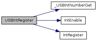
| void USBIntRegister | ( | uint32_t | ui32Base, |
| void(*)(void) | pfnHandler | ||
| ) |
Registers an interrupt handler for the USB controller.
| ui32Base | specifies the USB module base address. |
| pfnHandler | is a pointer to the function to be called when a USB interrupt occurs. |
This function registers the handler to be called when a USB interrupt occurs and enables the global USB interrupt in the interrupt controller. The specific desired USB interrupts must be enabled via a separate call to USBIntEnable(). It is the interrupt handler's responsibility to clear the interrupt sources via calls to USBIntStatusControl() and USBIntStatusEndpoint().
Definition at line 859 of file usb.c.
References _USBIntNumberGet(), ASSERT, IntEnable(), IntRegister(), and USB0_BASE.
| uint32_t USBIntStatusControl | ( | uint32_t | ui32Base | ) |
Returns the control interrupt status on a specified USB controller.
| ui32Base | specifies the USB module base address. |
This function reads control interrupt status for a USB controller. This call returns the current status for control interrupts only, the endpoint interrupt status is retrieved by calling USBIntStatusEndpoint(). The bit values returned are compared against the USB_INTCTRL_* values.
The following are the meanings of all USB_INCTRL_ flags and the modes for which they are valid. These values apply to any calls to USBIntStatusControl(), USBIntEnableControl(), and USBIntDisableControl(). Some of these flags are only valid in the following modes as indicated in the parentheses: Host, Device, and OTG.
Definition at line 635 of file usb.c.
References ASSERT, HWREG, HWREGB, USB0_BASE, USB_EPCISC_PF, USB_IDVRIS_ID, USB_INTCTRL_MODE_DETECT, USB_INTCTRL_POWER_FAULT, USB_O_EPCISC, USB_O_IDVISC, and USB_O_IS.
| uint32_t USBIntStatusEndpoint | ( | uint32_t | ui32Base | ) |
Returns the endpoint interrupt status on a specified USB controller.
| ui32Base | specifies the USB module base address. |
This function reads endpoint interrupt status for a USB controller. This call returns the current status for endpoint interrupts only, the control interrupt status is retrieved by calling USBIntStatusControl(). The bit values returned are compared against the USB_INTEP_* values. These values are grouped into classes for USB_INTEP_HOST_* and USB_INTEP_DEV_* values to handle both host and device modes with all endpoints.
Definition at line 783 of file usb.c.
References ASSERT, HWREGH, USB0_BASE, USB_INTEP_RX_SHIFT, USB_O_RXIS, and USB_O_TXIS.
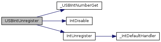
| void USBIntUnregister | ( | uint32_t | ui32Base | ) |
Unregisters an interrupt handler for the USB controller.
| ui32Base | specifies the USB module base address. |
This function unregisters the interrupt handler. This function also disables the USB interrupt in the interrupt controller.
Definition at line 899 of file usb.c.
References _USBIntNumberGet(), ASSERT, IntDisable(), IntUnregister(), and USB0_BASE.
| void USBModeConfig | ( | uint32_t | ui32Base, |
| uint32_t | ui32Mode | ||
| ) |
Change the operating mode of the USB controller.
| ui32Base | specifies the USB module base address. |
| ui32Mode | specifies the operating mode of the USB OTG pins. |
This function changes the operating modes of the USB controller. When operating in full OTG mode, the USB controller uses the VBUS and ID pins to detect mode and voltage changes. While these pins are primarily used in OTG mode, they can also affect the operation of host and device modes. In device mode, the USB controller can be configured to monitor or ignore VBUS. Monitoring VBUS allows the controller to determine if it has been disconnected from the host. In host mode, the USB controller uses the VBUS pin to detect loss of VBUS caused by excessive power draw due to a drop in the VBUS voltage. This call takes the place of USBHostMode(), USBDevMode(), and USBOTGMode(). The ui32Mode value should be one of the following values:
Example: Force device mode but allow monitoring of the USB VBUS pin.
//! //
//! // Force device mode but allow monitoring of VBUS for disconnect.
//! //
//! USBModeConfig(USB_MODE_DEVICE_VBUS);
//!
\return None.
Definition at line 4117 of file usb.c.
References ASSERT, HWREG, USB0_BASE, and USB_O_GPCS.
| uint32_t USBModeGet | ( | uint32_t | ui32Base | ) |
Returns the current operating mode of the controller.
| ui32Base | specifies the USB module base address. |
This function returns the current operating mode on USB controllers with OTG or Dual mode functionality.
For OTG controllers:
The function returns one of the following values on OTG controllers:
USB_OTG_MODE_ASIDE_HOST indicates that the controller is in host mode on the A-side of the cable.
USB_OTG_MODE_ASIDE_DEV indicates that the controller is in device mode on the A-side of the cable.
USB_OTG_MODE_BSIDE_HOST indicates that the controller is in host mode on the B-side of the cable.
USB_OTG_MODE_BSIDE_DEV indicates that the controller is in device mode on the B-side of the cable. If an OTG session request is started with no cable in place, this mode is the default.
USB_OTG_MODE_NONE indicates that the controller is not attempting to determine its role in the system.
For Dual Mode controllers:
The function returns one of the following values:
USB_DUAL_MODE_HOST indicates that the controller is acting as a host.
USB_DUAL_MODE_DEVICE indicates that the controller acting as a device.
USB_DUAL_MODE_NONE indicates that the controller is not active as either a host or device.
Definition at line 3898 of file usb.c.
References ASSERT, HWREGB, USB0_BASE, USB_DEVCTL_DEV, USB_DEVCTL_HOST, USB_DEVCTL_SESSION, USB_DEVCTL_VBUS_M, and USB_O_DEVCTL.
| uint32_t USBNumEndpointsGet | ( | uint32_t | ui32Base | ) |
Returns the number of USB endpoint pairs on the device.
| ui32Base | specifies the USB module base address. |
This function returns the number of endpoint pairs supported by the USB controller corresponding to the passed base address. The value returned is the number of IN or OUT endpoints available and does not include endpoint 0 (the control endpoint). For example, if 15 is returned, there are 15 IN and 15 OUT endpoints available in addition to endpoint 0.
Definition at line 4215 of file usb.c.
References HWREGB, USB_EPINFO_TXEP_M, and USB_O_EPINFO.
| void USBOTGMode | ( | uint32_t | ui32Base | ) |
Changes the mode of the USB controller to OTG.
| ui32Base | specifies the USB module base address. |
This function changes the mode of the USB controller to OTG mode. This function is only valid on microcontrollers that have the OTG capabilities.
Definition at line 4054 of file usb.c.
References ASSERT, HWREGB, USB0_BASE, and USB_O_GPCS.
| void USBOTGSessionRequest | ( | uint32_t | ui32Base, |
| bool | bStart | ||
| ) |
Starts or ends a session.
| ui32Base | specifies the USB module base address. |
| bStart | specifies if this call starts or ends a session. |
This function is used in OTG mode to start a session request or end a session. If the bStart parameter is set to true, then this function starts a session and if it is false it ends a session.
Definition at line 3805 of file usb.c.
References ASSERT, HWREGB, USB0_BASE, USB_DEVCTL_SESSION, and USB_O_DEVCTL.
| void USBPHYPowerOff | ( | uint32_t | ui32Base | ) |
Powers off the internal USB PHY.
| ui32Base | specifies the USB module base address. |
This function powers off the internal USB PHY, reducing the current consumption of the device. While in the powered-off state, the USB controller is unable to operate.
Definition at line 4141 of file usb.c.
References HWREGB, USB_O_POWER, and USB_POWER_PWRDNPHY.
| void USBPHYPowerOn | ( | uint32_t | ui32Base | ) |
Powers on the internal USB PHY.
| ui32Base | specifies the USB module base address. |
This function powers on the internal USB PHY, enabling it return to normal operation. By default, the PHY is powered on, so this function must only be called if USBPHYPowerOff() has previously been called.
Definition at line 4163 of file usb.c.
References HWREGB, USB_O_POWER, and USB_POWER_PWRDNPHY.
 1.8.9.1
