EE445M RTOS
Taken at the University of Texas Spring 2015
Adc_api

Macros

#define ADC_SEQ   (ADC_O_SSMUX0)
 
#define ADC_SEQ_STEP   (ADC_O_SSMUX1 - ADC_O_SSMUX0)
 
#define ADC_SSMUX   (ADC_O_SSMUX0 - ADC_O_SSMUX0)
 
#define ADC_SSEMUX   (ADC_O_SSEMUX0 - ADC_O_SSMUX0)
 
#define ADC_SSCTL   (ADC_O_SSCTL0 - ADC_O_SSMUX0)
 
#define ADC_SSFIFO   (ADC_O_SSFIFO0 - ADC_O_SSMUX0)
 
#define ADC_SSFSTAT   (ADC_O_SSFSTAT0 - ADC_O_SSMUX0)
 
#define ADC_SSOP   (ADC_O_SSOP0 - ADC_O_SSMUX0)
 
#define ADC_SSDC   (ADC_O_SSDC0 - ADC_O_SSMUX0)
 
#define ADC_SSTSH   (ADC_O_SSTSH0 - ADC_O_SSMUX0)
 

Functions

static uint_fast8_t _ADCIntNumberGet (uint32_t ui32Base, uint32_t ui32SequenceNum)
 
void ADCIntRegister (uint32_t ui32Base, uint32_t ui32SequenceNum, void(*pfnHandler)(void))
 
void ADCIntUnregister (uint32_t ui32Base, uint32_t ui32SequenceNum)
 
void ADCIntDisable (uint32_t ui32Base, uint32_t ui32SequenceNum)
 
void ADCIntEnable (uint32_t ui32Base, uint32_t ui32SequenceNum)
 
uint32_t ADCIntStatus (uint32_t ui32Base, uint32_t ui32SequenceNum, bool bMasked)
 
void ADCIntClear (uint32_t ui32Base, uint32_t ui32SequenceNum)
 
void ADCSequenceEnable (uint32_t ui32Base, uint32_t ui32SequenceNum)
 
void ADCSequenceDisable (uint32_t ui32Base, uint32_t ui32SequenceNum)
 
void ADCSequenceConfigure (uint32_t ui32Base, uint32_t ui32SequenceNum, uint32_t ui32Trigger, uint32_t ui32Priority)
 
void ADCSequenceStepConfigure (uint32_t ui32Base, uint32_t ui32SequenceNum, uint32_t ui32Step, uint32_t ui32Config)
 
int32_t ADCSequenceOverflow (uint32_t ui32Base, uint32_t ui32SequenceNum)
 
void ADCSequenceOverflowClear (uint32_t ui32Base, uint32_t ui32SequenceNum)
 
int32_t ADCSequenceUnderflow (uint32_t ui32Base, uint32_t ui32SequenceNum)
 
void ADCSequenceUnderflowClear (uint32_t ui32Base, uint32_t ui32SequenceNum)
 
int32_t ADCSequenceDataGet (uint32_t ui32Base, uint32_t ui32SequenceNum, uint32_t *pui32Buffer)
 
void ADCProcessorTrigger (uint32_t ui32Base, uint32_t ui32SequenceNum)
 
void ADCSoftwareOversampleConfigure (uint32_t ui32Base, uint32_t ui32SequenceNum, uint32_t ui32Factor)
 
void ADCSoftwareOversampleStepConfigure (uint32_t ui32Base, uint32_t ui32SequenceNum, uint32_t ui32Step, uint32_t ui32Config)
 
void ADCSoftwareOversampleDataGet (uint32_t ui32Base, uint32_t ui32SequenceNum, uint32_t *pui32Buffer, uint32_t ui32Count)
 
void ADCHardwareOversampleConfigure (uint32_t ui32Base, uint32_t ui32Factor)
 
void ADCComparatorConfigure (uint32_t ui32Base, uint32_t ui32Comp, uint32_t ui32Config)
 
void ADCComparatorRegionSet (uint32_t ui32Base, uint32_t ui32Comp, uint32_t ui32LowRef, uint32_t ui32HighRef)
 
void ADCComparatorReset (uint32_t ui32Base, uint32_t ui32Comp, bool bTrigger, bool bInterrupt)
 
void ADCComparatorIntDisable (uint32_t ui32Base, uint32_t ui32SequenceNum)
 
void ADCComparatorIntEnable (uint32_t ui32Base, uint32_t ui32SequenceNum)
 
uint32_t ADCComparatorIntStatus (uint32_t ui32Base)
 
void ADCComparatorIntClear (uint32_t ui32Base, uint32_t ui32Status)
 
void ADCIntDisableEx (uint32_t ui32Base, uint32_t ui32IntFlags)
 
void ADCIntEnableEx (uint32_t ui32Base, uint32_t ui32IntFlags)
 
uint32_t ADCIntStatusEx (uint32_t ui32Base, bool bMasked)
 
void ADCIntClearEx (uint32_t ui32Base, uint32_t ui32IntFlags)
 
void ADCReferenceSet (uint32_t ui32Base, uint32_t ui32Ref)
 
uint32_t ADCReferenceGet (uint32_t ui32Base)
 
void ADCPhaseDelaySet (uint32_t ui32Base, uint32_t ui32Phase)
 
uint32_t ADCPhaseDelayGet (uint32_t ui32Base)
 
void ADCSequenceDMAEnable (uint32_t ui32Base, uint32_t ui32SequenceNum)
 
void ADCSequenceDMADisable (uint32_t ui32Base, uint32_t ui32SequenceNum)
 
bool ADCBusy (uint32_t ui32Base)
 
void ADCClockConfigSet (uint32_t ui32Base, uint32_t ui32Config, uint32_t ui32ClockDiv)
 
uint32_t ADCClockConfigGet (uint32_t ui32Base, uint32_t *pui32ClockDiv)
 

Variables

static uint8_t g_pui8OversampleFactor [3]
 

Detailed Description

Macro Definition Documentation

#define ADC_SSCTL   (ADC_O_SSCTL0 - ADC_O_SSMUX0)

Definition at line 68 of file adc.c.

Referenced by ADCSequenceStepConfigure(), and ADCSoftwareOversampleStepConfigure().

#define ADC_SSDC   (ADC_O_SSDC0 - ADC_O_SSMUX0)

Definition at line 72 of file adc.c.

Referenced by ADCSequenceStepConfigure().

#define ADC_SSEMUX   (ADC_O_SSEMUX0 - ADC_O_SSMUX0)

Definition at line 67 of file adc.c.

Referenced by ADCSequenceStepConfigure(), and ADCSoftwareOversampleStepConfigure().

#define ADC_SSFIFO   (ADC_O_SSFIFO0 - ADC_O_SSMUX0)

Definition at line 69 of file adc.c.

Referenced by ADCSequenceDataGet(), and ADCSoftwareOversampleDataGet().

#define ADC_SSFSTAT   (ADC_O_SSFSTAT0 - ADC_O_SSMUX0)

Definition at line 70 of file adc.c.

Referenced by ADCSequenceDataGet().

#define ADC_SSMUX   (ADC_O_SSMUX0 - ADC_O_SSMUX0)

Definition at line 66 of file adc.c.

Referenced by ADCSequenceStepConfigure(), and ADCSoftwareOversampleStepConfigure().

#define ADC_SSOP   (ADC_O_SSOP0 - ADC_O_SSMUX0)

Definition at line 71 of file adc.c.

Referenced by ADCSequenceStepConfigure().

#define ADC_SSTSH   (ADC_O_SSTSH0 - ADC_O_SSMUX0)

Definition at line 73 of file adc.c.

Referenced by ADCSequenceStepConfigure().

Function Documentation

static uint_fast8_t _ADCIntNumberGet ( uint32_t  ui32Base,
uint32_t  ui32SequenceNum 
)
static

Returns the interrupt number for a given ADC base address and sequence number.

Parameters
ui32Baseis the base address of the ADC module.
ui32SequenceNumis the sample sequence number.

This function returns the interrupt number for the ADC module and sequence number provided in the ui32Base and ui32SequenceNum parameters.

Returns
Returns the ADC sequence interrupt number or 0 if the interrupt does not exist.

Definition at line 99 of file adc.c.

References ADC0_BASE, CLASS_IS_TM4C123, CLASS_IS_TM4C129, INT_ADC0SS0_TM4C123, INT_ADC0SS0_TM4C129, and INT_ADC1SS0_TM4C129.

Referenced by ADCIntRegister(), and ADCIntUnregister().

100 {
101  uint_fast8_t ui8Int;
102 
103  //
104  // Determine the interrupt to register based on the sequence number.
105  //
106  if(CLASS_IS_TM4C123)
107  {
108  ui8Int = ((ui32Base == ADC0_BASE) ?
109  (INT_ADC0SS0_TM4C123 + ui32SequenceNum) :
110  (INT_ADC0SS0_TM4C123 + ui32SequenceNum));
111  }
112  else if(CLASS_IS_TM4C129)
113  {
114  ui8Int = ((ui32Base == ADC0_BASE) ?
115  (INT_ADC0SS0_TM4C129 + ui32SequenceNum) :
116  (INT_ADC1SS0_TM4C129 + ui32SequenceNum));
117  }
118  else
119  {
120  ui8Int = 0;
121  }
122 
123  return(ui8Int);
124 }
#define INT_ADC0SS0_TM4C123
Definition: hw_ints.h:78
#define INT_ADC1SS0_TM4C129
Definition: hw_ints.h:222
#define ADC0_BASE
Definition: hw_memmap.h:89
#define INT_ADC0SS0_TM4C129
Definition: hw_ints.h:190
#define CLASS_IS_TM4C123
Definition: hw_types.h:93
#define CLASS_IS_TM4C129
Definition: hw_types.h:99

Here is the caller graph for this function:

bool ADCBusy ( uint32_t  ui32Base)

Determines whether the ADC is busy or not.

Parameters
ui32Baseis the base address of the ADC.

This function allows the caller to determine whether or not the ADC is currently sampling . If false is returned, then the ADC is not sampling data.

Use this function to detect that the ADC is finished sampling data before putting the device into deep sleep. Before using this function, it is highly recommended that the event trigger is changed to ADC_TRIGGER_NEVER on all enabled sequencers to prevent the ADC from starting after checking the busy status.

Returns
Returns true if the ADC is sampling or false if all samples are complete.

Definition at line 1834 of file adc.c.

References ADC0_BASE, ADC1_BASE, ADC_ACTSS_BUSY, ADC_O_ACTSS, ASSERT, and HWREG.

1835 {
1836  //
1837  // Check the argument.
1838  //
1839  ASSERT((ui32Base == ADC0_BASE) || (ui32Base == ADC1_BASE));
1840 
1841  //
1842  // Determine if the ADC is busy.
1843  //
1844  return((HWREG(ui32Base + ADC_O_ACTSS) & ADC_ACTSS_BUSY) ? true : false);
1845 }
#define HWREG(x)
Definition: hw_types.h:48
#define ADC1_BASE
Definition: hw_memmap.h:90
#define ADC_ACTSS_BUSY
Definition: hw_adc.h:147
#define ASSERT(expr)
Definition: debug.h:67
#define ADC0_BASE
Definition: hw_memmap.h:89
#define ADC_O_ACTSS
Definition: hw_adc.h:48
uint32_t ADCClockConfigGet ( uint32_t  ui32Base,
uint32_t *  pui32ClockDiv 
)

Returns the clock configuration for the ADC.

Parameters
ui32Baseis the base address of the ADC to configure, which must always be ADC0_BASE.
pui32ClockDivis a pointer to the input clock divider for the clock selected by the ADC_CLOCK_SRC in use by the ADCs.

This function returns the ADC clock configuration and the clock divider for the ADCs.

Example: Read the current ADC clock configuration.

//! uint32_t ui32Config, ui32ClockDiv;
//!
//! //
//! // Read the current ADC clock configuration.
//! //
//! ui32Config = ADCClockConfigGet(ADC0_BASE, &ui32ClockDiv);
//! 
\return The current clock configuration of the ADC defined as a combination
of one of \b ADC_CLOCK_SRC_PLL, \b ADC_CLOCK_SRC_PIOSC,
\b ADC_CLOCK_SRC_MOSC, or \b ADC_CLOCK_SRC_ALTCLK logical ORed with one of
\b ADC_CLOCK_RATE_FULL, \b ADC_CLOCK_RATE_HALF, \b ADC_CLOCK_RATE_QUARTER,
or \b ADC_CLOCK_RATE_EIGHTH.  See ADCClockConfigSet() for more information
on these values.  

Definition at line 1978 of file adc.c.

References ADC0_BASE, ADC_CC_CLKDIV_M, ADC_CC_CLKDIV_S, ADC_O_CC, ADC_O_PC, ADC_PC_SR_M, ASSERT, and HWREG.

1979 {
1980  uint32_t ui32Config;
1981 
1982  //
1983  // Check the argument.
1984  //
1985  ASSERT(ui32Base == ADC0_BASE);
1986 
1987  //
1988  // Read the current configuration.
1989  //
1990  ui32Config = HWREG(ui32Base + ADC_O_CC);
1991 
1992  //
1993  // If the clock divider was requested provide the current value.
1994  //
1995  if(pui32ClockDiv)
1996  {
1997  *pui32ClockDiv =
1998  ((ui32Config & ADC_CC_CLKDIV_M) >> ADC_CC_CLKDIV_S) + 1;
1999  }
2000 
2001  //
2002  // Clear out the divider bits.
2003  //
2004  ui32Config &= ~ADC_CC_CLKDIV_M;
2005 
2006  //
2007  // Add in the sample interval to the configuration.
2008  //
2009  ui32Config = (HWREG(ui32Base + ADC_O_PC) & ADC_PC_SR_M) << 4;
2010 
2011  return(ui32Config);
2012 }
#define ADC_O_CC
Definition: hw_adc.h:140
#define HWREG(x)
Definition: hw_types.h:48
#define ADC_CC_CLKDIV_S
Definition: hw_adc.h:1305
#define ASSERT(expr)
Definition: debug.h:67
#define ADC_CC_CLKDIV_M
Definition: hw_adc.h:1300
#define ADC0_BASE
Definition: hw_memmap.h:89
#define ADC_O_PC
Definition: hw_adc.h:139
#define ADC_PC_SR_M
Definition: hw_adc.h:1271
void ADCClockConfigSet ( uint32_t  ui32Base,
uint32_t  ui32Config,
uint32_t  ui32ClockDiv 
)

Sets the clock configuration for the ADC.

Parameters
ui32Baseis the base address of the ADC to configure, which must always be ADC0_BASE.
ui32Configis a combination of the ADC_CLOCK_SRC_ and ADC_CLOCK_RATE_* values used to configure the ADC clock input.
ui32ClockDivis the input clock divider for the clock selected by the ADC_CLOCK_SRC value.

This function is used to configure the input clock to the ADC modules. The clock configuration is shared across ADC units so ui32Base must always be ADC0_BASE. The ui32Config value is logical OR of one of the ADC_CLOCK_RATE_ and one of the ADC_CLOCK_SRC_ values defined below. The ADC_CLOCK_SRC_* values determine the input clock for the ADC. Not all values are available on all devices so check the device data sheet to determine value configuration options. Regardless of the source, the final frequency for TM4C123x devices must be 16 MHz and for TM4C129x parts after dividing must be between 16 and 32 MHz.

Note
For TM4C123x devices, if the PLL is enabled, the PLL/25 is used as the ADC clock unless ADC_CLOCK_SRC_PIOSC is specified. If the PLL is disabled, the MOSC is used as the clock source unless ADC_CLOCK_SRC_PIOSC is specified.
  • ADC_CLOCK_SRC_PLL - The main PLL output (TM4x129 class only).
  • ADC_CLOCK_SRC_PIOSC - The internal PIOSC at 16 MHz.
  • ADC_CLOCK_SRC_ALTCLK - The output of the ALTCLK in the system control module (TM4x129 class only).
  • ADC_CLOCK_SRC_MOSC - The external MOSC (TM4x129 class only).

ADC_CLOCK_RATE values control how often samples are provided back to the application. The values are the following:

  • ADC_CLOCK_RATE_FULL - All samples.
  • ADC_CLOCK_RATE_HALF - Every other sample.
  • ADC_CLOCK_RATE_QUARTER - Every fourth sample.
  • ADC_CLOCK_RATE_EIGHTH - Every either sample.

The ui32ClockDiv parameter allows for dividing a higher frequency down into the valid range for the ADCs. This parameter is typically only used ADC_CLOCK_SRC_PLL option because it is the only clock value that can be with the in the correct range to use the divider. The actual value ranges from 1 to 64.

Example: ADC Clock Configurations

//!
//! //
//! // Configure the ADC to use PIOSC divided by one (16 MHz) and sample at
//! // half the rate.
//! //
//! ADCClockConfigSet(ADC0_BASE, ADC_CLOCK_SRC_PIOSC | ADC_CLOCK_RATE_HALF, 1);
//!
//! ...
//!
//! //
//! // Configure the ADC to use PLL at 480 MHz divided by 24 to get an ADC
//! // clock of 20 MHz.
//! //
//! ADCClockConfigSet(ADC0_BASE, ADC_CLOCK_SRC_PLL | ADC_CLOCK_RATE_FULL, 24);
//! 
\return None.  

Definition at line 1916 of file adc.c.

References ADC0_BASE, ADC_CC_CLKDIV_M, ADC_CC_CLKDIV_S, ADC_CC_CS_M, ADC_CLOCK_RATE_FULL, ADC_O_CC, ADC_O_PC, ADC_PC_SR_M, ASSERT, and HWREG.

1918 {
1919  //
1920  // Check the argument.
1921  //
1922  ASSERT(ui32Base == ADC0_BASE);
1923 
1924  //
1925  // A rate must be supplied.
1926  //
1927  ASSERT((ui32Config & ADC_CLOCK_RATE_FULL) != 0);
1928 
1929  //
1930  // Clock must be valid divider.
1931  //
1932  ASSERT(((ui32ClockDiv - 1) & ~ADC_CC_CLKDIV_M) == 0);
1933 
1934  //
1935  // Write the sample conversion rate.
1936  //
1937  HWREG(ui32Base + ADC_O_PC) = (ui32Config >> 4) & ADC_PC_SR_M;
1938 
1939  //
1940  // Write the clock select and divider.
1941  //
1942  HWREG(ui32Base + ADC_O_CC) = (ui32Config & ADC_CC_CS_M) |
1943  (((ui32ClockDiv - 1) << ADC_CC_CLKDIV_S)) ;
1944 }
#define ADC_O_CC
Definition: hw_adc.h:140
#define HWREG(x)
Definition: hw_types.h:48
#define ADC_CC_CLKDIV_S
Definition: hw_adc.h:1305
#define ASSERT(expr)
Definition: debug.h:67
#define ADC_CLOCK_RATE_FULL
Definition: adc.h:235
#define ADC_CC_CLKDIV_M
Definition: hw_adc.h:1300
#define ADC0_BASE
Definition: hw_memmap.h:89
#define ADC_CC_CS_M
Definition: hw_adc.h:1301
#define ADC_O_PC
Definition: hw_adc.h:139
#define ADC_PC_SR_M
Definition: hw_adc.h:1271
void ADCComparatorConfigure ( uint32_t  ui32Base,
uint32_t  ui32Comp,
uint32_t  ui32Config 
)

Configures an ADC digital comparator.

Parameters
ui32Baseis the base address of the ADC module.
ui32Compis the index of the comparator to configure.
ui32Configis the configuration of the comparator.

This function configures a comparator. The ui32Config parameter is the result of a logical OR operation between the ADC_COMP_TRIG_xxx, and ADC_COMP_INT_xxx values.

The ADC_COMP_TRIG_xxx term can take on the following values:

  • ADC_COMP_TRIG_NONE to never trigger PWM fault condition.
  • ADC_COMP_TRIG_LOW_ALWAYS to always trigger PWM fault condition when ADC output is in the low-band.
  • ADC_COMP_TRIG_LOW_ONCE to trigger PWM fault condition once when ADC output transitions into the low-band.
  • ADC_COMP_TRIG_LOW_HALWAYS to always trigger PWM fault condition when ADC output is in the low-band only if ADC output has been in the high-band since the last trigger output.
  • ADC_COMP_TRIG_LOW_HONCE to trigger PWM fault condition once when ADC output transitions into low-band only if ADC output has been in the high-band since the last trigger output.
  • ADC_COMP_TRIG_MID_ALWAYS to always trigger PWM fault condition when ADC output is in the mid-band.
  • ADC_COMP_TRIG_MID_ONCE to trigger PWM fault condition once when ADC output transitions into the mid-band.
  • ADC_COMP_TRIG_HIGH_ALWAYS to always trigger PWM fault condition when ADC output is in the high-band.
  • ADC_COMP_TRIG_HIGH_ONCE to trigger PWM fault condition once when ADC output transitions into the high-band.
  • ADC_COMP_TRIG_HIGH_HALWAYS to always trigger PWM fault condition when ADC output is in the high-band only if ADC output has been in the low-band since the last trigger output.
  • ADC_COMP_TRIG_HIGH_HONCE to trigger PWM fault condition once when ADC output transitions into high-band only if ADC output has been in the low-band since the last trigger output.

The ADC_COMP_INT_xxx term can take on the following values:

  • ADC_COMP_INT_NONE to never generate ADC interrupt.
  • ADC_COMP_INT_LOW_ALWAYS to always generate ADC interrupt when ADC output is in the low-band.
  • ADC_COMP_INT_LOW_ONCE to generate ADC interrupt once when ADC output transitions into the low-band.
  • ADC_COMP_INT_LOW_HALWAYS to always generate ADC interrupt when ADC output is in the low-band only if ADC output has been in the high-band since the last trigger output.
  • ADC_COMP_INT_LOW_HONCE to generate ADC interrupt once when ADC output transitions into low-band only if ADC output has been in the high-band since the last trigger output.
  • ADC_COMP_INT_MID_ALWAYS to always generate ADC interrupt when ADC output is in the mid-band.
  • ADC_COMP_INT_MID_ONCE to generate ADC interrupt once when ADC output transitions into the mid-band.
  • ADC_COMP_INT_HIGH_ALWAYS to always generate ADC interrupt when ADC output is in the high-band.
  • ADC_COMP_INT_HIGH_ONCE to generate ADC interrupt once when ADC output transitions into the high-band.
  • ADC_COMP_INT_HIGH_HALWAYS to always generate ADC interrupt when ADC output is in the high-band only if ADC output has been in the low-band since the last trigger output.
  • ADC_COMP_INT_HIGH_HONCE to generate ADC interrupt once when ADC output transitions into high-band only if ADC output has been in the low-band since the last trigger output.
Returns
None.

Definition at line 1222 of file adc.c.

References ADC0_BASE, ADC1_BASE, ADC_O_DCCTL0, ASSERT, and HWREG.

1224 {
1225  //
1226  // Check the arguments.
1227  //
1228  ASSERT((ui32Base == ADC0_BASE) || (ui32Base == ADC1_BASE));
1229  ASSERT(ui32Comp < 8);
1230 
1231  //
1232  // Save the new setting.
1233  //
1234  HWREG(ui32Base + ADC_O_DCCTL0 + (ui32Comp * 4)) = ui32Config;
1235 }
#define HWREG(x)
Definition: hw_types.h:48
#define ADC1_BASE
Definition: hw_memmap.h:90
#define ASSERT(expr)
Definition: debug.h:67
#define ADC0_BASE
Definition: hw_memmap.h:89
#define ADC_O_DCCTL0
Definition: hw_adc.h:122
void ADCComparatorIntClear ( uint32_t  ui32Base,
uint32_t  ui32Status 
)

Clears sample sequence comparator interrupt source.

Parameters
ui32Baseis the base address of the ADC module.
ui32Statusis the bit-mapped interrupts status to clear.

The specified interrupt status is cleared.

Returns
None.

Definition at line 1414 of file adc.c.

References ADC0_BASE, ADC1_BASE, ADC_O_DCISC, ASSERT, and HWREG.

1415 {
1416  //
1417  // Check the arguments.
1418  //
1419  ASSERT((ui32Base == ADC0_BASE) || (ui32Base == ADC1_BASE));
1420 
1421  //
1422  // Clear the interrupt.
1423  //
1424  HWREG(ui32Base + ADC_O_DCISC) = ui32Status;
1425 }
#define HWREG(x)
Definition: hw_types.h:48
#define ADC1_BASE
Definition: hw_memmap.h:90
#define ASSERT(expr)
Definition: debug.h:67
#define ADC0_BASE
Definition: hw_memmap.h:89
#define ADC_O_DCISC
Definition: hw_adc.h:61
void ADCComparatorIntDisable ( uint32_t  ui32Base,
uint32_t  ui32SequenceNum 
)

Disables a sample sequence comparator interrupt.

Parameters
ui32Baseis the base address of the ADC module.
ui32SequenceNumis the sample sequence number.

This function disables the requested sample sequence comparator interrupt.

Returns
None.

Definition at line 1334 of file adc.c.

References ADC0_BASE, ADC1_BASE, ADC_O_IM, ASSERT, and HWREG.

1335 {
1336  //
1337  // Check the arguments.
1338  //
1339  ASSERT((ui32Base == ADC0_BASE) || (ui32Base == ADC1_BASE));
1340  ASSERT(ui32SequenceNum < 4);
1341 
1342  //
1343  // Disable this sample sequence comparator interrupt.
1344  //
1345  HWREG(ui32Base + ADC_O_IM) &= ~(0x10000 << ui32SequenceNum);
1346 }
#define ADC_O_IM
Definition: hw_adc.h:50
#define HWREG(x)
Definition: hw_types.h:48
#define ADC1_BASE
Definition: hw_memmap.h:90
#define ASSERT(expr)
Definition: debug.h:67
#define ADC0_BASE
Definition: hw_memmap.h:89
void ADCComparatorIntEnable ( uint32_t  ui32Base,
uint32_t  ui32SequenceNum 
)

Enables a sample sequence comparator interrupt.

Parameters
ui32Baseis the base address of the ADC module.
ui32SequenceNumis the sample sequence number.

This function enables the requested sample sequence comparator interrupt.

Returns
None.

Definition at line 1361 of file adc.c.

References ADC0_BASE, ADC1_BASE, ADC_O_IM, ASSERT, and HWREG.

1362 {
1363  //
1364  // Check the arguments.
1365  //
1366  ASSERT((ui32Base == ADC0_BASE) || (ui32Base == ADC1_BASE));
1367  ASSERT(ui32SequenceNum < 4);
1368 
1369  //
1370  // Enable this sample sequence interrupt.
1371  //
1372  HWREG(ui32Base + ADC_O_IM) |= 0x10000 << ui32SequenceNum;
1373 }
#define ADC_O_IM
Definition: hw_adc.h:50
#define HWREG(x)
Definition: hw_types.h:48
#define ADC1_BASE
Definition: hw_memmap.h:90
#define ASSERT(expr)
Definition: debug.h:67
#define ADC0_BASE
Definition: hw_memmap.h:89
uint32_t ADCComparatorIntStatus ( uint32_t  ui32Base)

Gets the current comparator interrupt status.

Parameters
ui32Baseis the base address of the ADC module.

This function returns the digital comparator interrupt status bits. This status is sequence agnostic.

Returns
The current comparator interrupt status.

Definition at line 1388 of file adc.c.

References ADC0_BASE, ADC1_BASE, ADC_O_DCISC, ASSERT, and HWREG.

1389 {
1390  //
1391  // Check the arguments.
1392  //
1393  ASSERT((ui32Base == ADC0_BASE) || (ui32Base == ADC1_BASE));
1394 
1395  //
1396  // Return the digital comparator interrupt status.
1397  //
1398  return(HWREG(ui32Base + ADC_O_DCISC));
1399 }
#define HWREG(x)
Definition: hw_types.h:48
#define ADC1_BASE
Definition: hw_memmap.h:90
#define ASSERT(expr)
Definition: debug.h:67
#define ADC0_BASE
Definition: hw_memmap.h:89
#define ADC_O_DCISC
Definition: hw_adc.h:61
void ADCComparatorRegionSet ( uint32_t  ui32Base,
uint32_t  ui32Comp,
uint32_t  ui32LowRef,
uint32_t  ui32HighRef 
)

Defines the ADC digital comparator regions.

Parameters
ui32Baseis the base address of the ADC module.
ui32Compis the index of the comparator to configure.
ui32LowRefis the reference point for the low/mid band threshold.
ui32HighRefis the reference point for the mid/high band threshold.

The ADC digital comparator operation is based on three ADC value regions:

  • low-band is defined as any ADC value less than or equal to the ui32LowRef value.
  • mid-band is defined as any ADC value greater than the ui32LowRef value but less than or equal to the ui32HighRef value.
  • high-band is defined as any ADC value greater than the ui32HighRef value.
Returns
None.

Definition at line 1258 of file adc.c.

References ADC0_BASE, ADC1_BASE, ADC_O_DCCMP0, ASSERT, and HWREG.

1260 {
1261  //
1262  // Check the arguments.
1263  //
1264  ASSERT((ui32Base == ADC0_BASE) || (ui32Base == ADC1_BASE));
1265  ASSERT(ui32Comp < 8);
1266  ASSERT((ui32LowRef < 4096) && (ui32LowRef <= ui32HighRef));
1267  ASSERT(ui32HighRef < 4096);
1268 
1269  //
1270  // Save the new region settings.
1271  //
1272  HWREG(ui32Base + ADC_O_DCCMP0 + (ui32Comp * 4)) = ((ui32HighRef << 16) |
1273  ui32LowRef);
1274 }
#define HWREG(x)
Definition: hw_types.h:48
#define ADC1_BASE
Definition: hw_memmap.h:90
#define ASSERT(expr)
Definition: debug.h:67
#define ADC0_BASE
Definition: hw_memmap.h:89
#define ADC_O_DCCMP0
Definition: hw_adc.h:130
void ADCComparatorReset ( uint32_t  ui32Base,
uint32_t  ui32Comp,
bool  bTrigger,
bool  bInterrupt 
)

Resets the current ADC digital comparator conditions.

Parameters
ui32Baseis the base address of the ADC module.
ui32Compis the index of the comparator.
bTriggeris the flag to indicate reset of Trigger conditions.
bInterruptis the flag to indicate reset of Interrupt conditions.

Because the digital comparator uses current and previous ADC values, this function allows the comparator to be reset to its initial value to prevent stale data from being used when a sequence is enabled.

Returns
None.

Definition at line 1293 of file adc.c.

References ADC0_BASE, ADC1_BASE, ADC_O_DCRIC, ASSERT, and HWREG.

1295 {
1296  uint32_t ui32Temp;
1297 
1298  //
1299  // Check the arguments.
1300  //
1301  ASSERT((ui32Base == ADC0_BASE) || (ui32Base == ADC1_BASE));
1302  ASSERT(ui32Comp < 8);
1303 
1304  //
1305  // Set the appropriate bits to reset the trigger and/or interrupt
1306  // comparator conditions.
1307  //
1308  ui32Temp = 0;
1309  if(bTrigger)
1310  {
1311  ui32Temp |= (1 << (16 + ui32Comp));
1312  }
1313  if(bInterrupt)
1314  {
1315  ui32Temp |= (1 << ui32Comp);
1316  }
1317 
1318  HWREG(ui32Base + ADC_O_DCRIC) = ui32Temp;
1319 }
#define HWREG(x)
Definition: hw_types.h:48
#define ADC1_BASE
Definition: hw_memmap.h:90
#define ASSERT(expr)
Definition: debug.h:67
#define ADC0_BASE
Definition: hw_memmap.h:89
#define ADC_O_DCRIC
Definition: hw_adc.h:120
void ADCHardwareOversampleConfigure ( uint32_t  ui32Base,
uint32_t  ui32Factor 
)

Configures the hardware oversampling factor of the ADC.

Parameters
ui32Baseis the base address of the ADC module.
ui32Factoris the number of samples to be averaged.

This function configures the hardware oversampling for the ADC, which can be used to provide better resolution on the sampled data. Oversampling is accomplished by averaging multiple samples from the same analog input. Six different oversampling rates are supported; 2x, 4x, 8x, 16x, 32x, and 64x. Specifying an oversampling factor of zero disables hardware oversampling.

Hardware oversampling applies uniformly to all sample sequencers. It does not reduce the depth of the sample sequencers like the software oversampling APIs; each sample written into the sample sequencer FIFO is a fully oversampled analog input reading.

Enabling hardware averaging increases the precision of the ADC at the cost of throughput. For example, enabling 4x oversampling reduces the throughput of a 250 k samples/second ADC to 62.5 k samples/second.

Returns
None.

Definition at line 1124 of file adc.c.

References ADC0_BASE, ADC1_BASE, ADC_O_SAC, ASSERT, and HWREG.

1125 {
1126  uint32_t ui32Value;
1127 
1128  //
1129  // Check the arguments.
1130  //
1131  ASSERT((ui32Base == ADC0_BASE) || (ui32Base == ADC1_BASE));
1132  ASSERT(((ui32Factor == 0) || (ui32Factor == 2) || (ui32Factor == 4) ||
1133  (ui32Factor == 8) || (ui32Factor == 16) || (ui32Factor == 32) ||
1134  (ui32Factor == 64)));
1135 
1136  //
1137  // Convert the oversampling factor to a shift factor.
1138  //
1139  for(ui32Value = 0, ui32Factor >>= 1; ui32Factor;
1140  ui32Value++, ui32Factor >>= 1)
1141  {
1142  }
1143 
1144  //
1145  // Write the shift factor to the ADC to configure the hardware oversampler.
1146  //
1147  HWREG(ui32Base + ADC_O_SAC) = ui32Value;
1148 }
#define HWREG(x)
Definition: hw_types.h:48
#define ADC1_BASE
Definition: hw_memmap.h:90
#define ASSERT(expr)
Definition: debug.h:67
#define ADC0_BASE
Definition: hw_memmap.h:89
#define ADC_O_SAC
Definition: hw_adc.h:60
void ADCIntClear ( uint32_t  ui32Base,
uint32_t  ui32SequenceNum 
)

Clears sample sequence interrupt source.

Parameters
ui32Baseis the base address of the ADC module.
ui32SequenceNumis the sample sequence number.

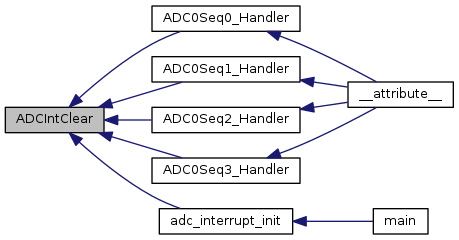
The specified sample sequence interrupt is cleared, so that it no longer asserts. This function must be called in the interrupt handler to keep the interrupt from being triggered again immediately upon exit.

Note
Because there is a write buffer in the Cortex-M processor, it may take several clock cycles before the interrupt source is actually cleared. Therefore, it is recommended that the interrupt source be cleared early in the interrupt handler (as opposed to the very last action) to avoid returning from the interrupt handler before the interrupt source is actually cleared. Failure to do so may result in the interrupt handler being immediately reentered (because the interrupt controller still sees the interrupt source asserted).
Returns
None.

Definition at line 363 of file adc.c.

References ADC0_BASE, ADC1_BASE, ADC_O_ISC, ASSERT, and HWREG.

Referenced by ADC0Seq0_Handler(), ADC0Seq1_Handler(), ADC0Seq2_Handler(), ADC0Seq3_Handler(), and adc_interrupt_init().

364 {
365  //
366  // Check the arguments.
367  //
368  ASSERT((ui32Base == ADC0_BASE) || (ui32Base == ADC1_BASE));
369  ASSERT(ui32SequenceNum < 4);
370 
371  //
372  // Clear the interrupt.
373  //
374  HWREG(ui32Base + ADC_O_ISC) = 1 << ui32SequenceNum;
375 }
#define HWREG(x)
Definition: hw_types.h:48
#define ADC1_BASE
Definition: hw_memmap.h:90
#define ASSERT(expr)
Definition: debug.h:67
#define ADC0_BASE
Definition: hw_memmap.h:89
#define ADC_O_ISC
Definition: hw_adc.h:51

Here is the caller graph for this function:

void ADCIntClearEx ( uint32_t  ui32Base,
uint32_t  ui32IntFlags 
)

Clears the specified ADC interrupt sources.

Parameters
ui32Baseis the base address of the ADC port.
ui32IntFlagsis the bit mask of the interrupt sources to disable.

Clears the interrupt for the specified interrupt source(s).

The ui32IntFlags parameter is the logical OR of the ADC_INT_* values. See the ADCIntEnableEx() function for the list of possible ADC_INT* values.

Note
Because there is a write buffer in the Cortex-M processor, it may take several clock cycles before the interrupt source is actually cleared. Therefore, it is recommended that the interrupt source be cleared early in the interrupt handler (as opposed to the very last action) to avoid returning from the interrupt handler before the interrupt source is actually cleared. Failure to do so may result in the interrupt handler being immediately reentered (because the interrupt controller still sees the interrupt source asserted).
Returns
None.

Definition at line 1606 of file adc.c.

References ADC_O_ISC, and HWREG.

1607 {
1608  HWREG(ui32Base + ADC_O_ISC) |= ui32IntFlags;
1609 }
#define HWREG(x)
Definition: hw_types.h:48
#define ADC_O_ISC
Definition: hw_adc.h:51
void ADCIntDisable ( uint32_t  ui32Base,
uint32_t  ui32SequenceNum 
)

Disables a sample sequence interrupt.

Parameters
ui32Baseis the base address of the ADC module.
ui32SequenceNumis the sample sequence number.

This function disables the requested sample sequence interrupt.

Returns
None.

Definition at line 234 of file adc.c.

References ADC0_BASE, ADC1_BASE, ADC_O_IM, ASSERT, and HWREG.

235 {
236  //
237  // Check the arguments.
238  //
239  ASSERT((ui32Base == ADC0_BASE) || (ui32Base == ADC1_BASE));
240  ASSERT(ui32SequenceNum < 4);
241 
242  //
243  // Disable this sample sequence interrupt.
244  //
245  HWREG(ui32Base + ADC_O_IM) &= ~(1 << ui32SequenceNum);
246 }
#define ADC_O_IM
Definition: hw_adc.h:50
#define HWREG(x)
Definition: hw_types.h:48
#define ADC1_BASE
Definition: hw_memmap.h:90
#define ASSERT(expr)
Definition: debug.h:67
#define ADC0_BASE
Definition: hw_memmap.h:89
void ADCIntDisableEx ( uint32_t  ui32Base,
uint32_t  ui32IntFlags 
)

Disables ADC interrupt sources.

Parameters
ui32Baseis the base address of the ADC module.
ui32IntFlagsis the bit mask of the interrupt sources to disable.

This function disables the indicated ADC interrupt sources. Only the sources that are enabled can be reflected to the processor interrupt; disabled sources have no effect on the processor.

The ui32IntFlags parameter is the logical OR of any of the following:

  • ADC_INT_SS0 - interrupt due to ADC sample sequence 0.
  • ADC_INT_SS1 - interrupt due to ADC sample sequence 1.
  • ADC_INT_SS2 - interrupt due to ADC sample sequence 2.
  • ADC_INT_SS3 - interrupt due to ADC sample sequence 3.
  • ADC_INT_DMA_SS0 - interrupt due to DMA on ADC sample sequence 0.
  • ADC_INT_DMA_SS1 - interrupt due to DMA on ADC sample sequence 1.
  • ADC_INT_DMA_SS2 - interrupt due to DMA on ADC sample sequence 2.
  • ADC_INT_DMA_SS3 - interrupt due to DMA on ADC sample sequence 3.
  • ADC_INT_DCON_SS0 - interrupt due to digital comparator on ADC sample sequence 0.
  • ADC_INT_DCON_SS1 - interrupt due to digital comparator on ADC sample sequence 1.
  • ADC_INT_DCON_SS2 - interrupt due to digital comparator on ADC sample sequence 2.
  • ADC_INT_DCON_SS3 - interrupt due to digital comparator on ADC sample sequence 3.
Returns
None.

Definition at line 1461 of file adc.c.

References ADC0_BASE, ADC1_BASE, ADC_O_IM, ASSERT, and HWREG.

1462 {
1463  //
1464  // Check the arguments.
1465  //
1466  ASSERT((ui32Base == ADC0_BASE) || (ui32Base == ADC1_BASE));
1467 
1468  //
1469  // Disable the requested interrupts.
1470  //
1471  HWREG(ui32Base + ADC_O_IM) &= ~ui32IntFlags;
1472 }
#define ADC_O_IM
Definition: hw_adc.h:50
#define HWREG(x)
Definition: hw_types.h:48
#define ADC1_BASE
Definition: hw_memmap.h:90
#define ASSERT(expr)
Definition: debug.h:67
#define ADC0_BASE
Definition: hw_memmap.h:89
void ADCIntEnable ( uint32_t  ui32Base,
uint32_t  ui32SequenceNum 
)

Enables a sample sequence interrupt.

Parameters
ui32Baseis the base address of the ADC module.
ui32SequenceNumis the sample sequence number.

This function enables the requested sample sequence interrupt. Any outstanding interrupts are cleared before enabling the sample sequence interrupt.

Returns
None.

Definition at line 263 of file adc.c.

References ADC0_BASE, ADC1_BASE, ADC_O_IM, ADC_O_ISC, ASSERT, and HWREG.

Referenced by adc_channel_init().

264 {
265  //
266  // Check the arguments.
267  //
268  ASSERT((ui32Base == ADC0_BASE) || (ui32Base == ADC1_BASE));
269  ASSERT(ui32SequenceNum < 4);
270 
271  //
272  // Clear any outstanding interrupts on this sample sequence.
273  //
274  HWREG(ui32Base + ADC_O_ISC) = 1 << ui32SequenceNum;
275 
276  //
277  // Enable this sample sequence interrupt.
278  //
279  HWREG(ui32Base + ADC_O_IM) |= 1 << ui32SequenceNum;
280 }
#define ADC_O_IM
Definition: hw_adc.h:50
#define HWREG(x)
Definition: hw_types.h:48
#define ADC1_BASE
Definition: hw_memmap.h:90
#define ASSERT(expr)
Definition: debug.h:67
#define ADC0_BASE
Definition: hw_memmap.h:89
#define ADC_O_ISC
Definition: hw_adc.h:51

Here is the caller graph for this function:

void ADCIntEnableEx ( uint32_t  ui32Base,
uint32_t  ui32IntFlags 
)

Enables ADC interrupt sources.

Parameters
ui32Baseis the base address of the ADC module.
ui32IntFlagsis the bit mask of the interrupt sources to disable.

This function enables the indicated ADC interrupt sources. Only the sources that are enabled can be reflected to the processor interrupt; disabled sources have no effect on the processor.

The ui32IntFlags parameter is the logical OR of any of the following:

  • ADC_INT_SS0 - interrupt due to ADC sample sequence 0.
  • ADC_INT_SS1 - interrupt due to ADC sample sequence 1.
  • ADC_INT_SS2 - interrupt due to ADC sample sequence 2.
  • ADC_INT_SS3 - interrupt due to ADC sample sequence 3.
  • ADC_INT_DMA_SS0 - interrupt due to DMA on ADC sample sequence 0.
  • ADC_INT_DMA_SS1 - interrupt due to DMA on ADC sample sequence 1.
  • ADC_INT_DMA_SS2 - interrupt due to DMA on ADC sample sequence 2.
  • ADC_INT_DMA_SS3 - interrupt due to DMA on ADC sample sequence 3.
  • ADC_INT_DCON_SS0 - interrupt due to digital comparator on ADC sample sequence 0.
  • ADC_INT_DCON_SS1 - interrupt due to digital comparator on ADC sample sequence 1.
  • ADC_INT_DCON_SS2 - interrupt due to digital comparator on ADC sample sequence 2.
  • ADC_INT_DCON_SS3 - interrupt due to digital comparator on ADC sample sequence 3.
Returns
None.

Definition at line 1508 of file adc.c.

References ADC0_BASE, ADC1_BASE, ADC_O_IM, ASSERT, and HWREG.

1509 {
1510  //
1511  // Check the arguments.
1512  //
1513  ASSERT((ui32Base == ADC0_BASE) || (ui32Base == ADC1_BASE));
1514 
1515  //
1516  // Enable the requested interrupts.
1517  //
1518  HWREG(ui32Base + ADC_O_IM) |= ui32IntFlags;
1519 }
#define ADC_O_IM
Definition: hw_adc.h:50
#define HWREG(x)
Definition: hw_types.h:48
#define ADC1_BASE
Definition: hw_memmap.h:90
#define ASSERT(expr)
Definition: debug.h:67
#define ADC0_BASE
Definition: hw_memmap.h:89
void ADCIntRegister ( uint32_t  ui32Base,
uint32_t  ui32SequenceNum,
void(*)(void)  pfnHandler 
)

Registers an interrupt handler for an ADC interrupt.

Parameters
ui32Baseis the base address of the ADC module.
ui32SequenceNumis the sample sequence number.
pfnHandleris a pointer to the function to be called when the ADC sample sequence interrupt occurs.

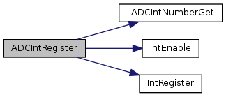
This function sets the handler to be called when a sample sequence interrupt occurs. This function enables the global interrupt in the interrupt controller; the sequence interrupt must be enabled with ADCIntEnable(). It is the interrupt handler's responsibility to clear the interrupt source via ADCIntClear().

See also
IntRegister() for important information about registering interrupt handlers.
Returns
None.

Definition at line 148 of file adc.c.

References _ADCIntNumberGet(), ADC0_BASE, ADC1_BASE, ASSERT, IntEnable(), and IntRegister().

150 {
151  uint_fast8_t ui8Int;
152 
153  //
154  // Check the arguments.
155  //
156  ASSERT((ui32Base == ADC0_BASE) || (ui32Base == ADC1_BASE));
157  ASSERT(ui32SequenceNum < 4);
158 
159  //
160  // Determine the interrupt to register based on the sequence number.
161  //
162  ui8Int = _ADCIntNumberGet(ui32Base, ui32SequenceNum);
163  ASSERT(ui8Int != 0);
164 
165  //
166  // Register the interrupt handler.
167  //
168  IntRegister(ui8Int, pfnHandler);
169 
170  //
171  // Enable the timer interrupt.
172  //
173  IntEnable(ui8Int);
174 }
#define ADC1_BASE
Definition: hw_memmap.h:90
#define ASSERT(expr)
Definition: debug.h:67
static uint_fast8_t _ADCIntNumberGet(uint32_t ui32Base, uint32_t ui32SequenceNum)
Definition: adc.c:99
#define ADC0_BASE
Definition: hw_memmap.h:89
void IntRegister(uint32_t ui32Interrupt, void(*pfnHandler)(void))
Definition: interrupt.c:309
void IntEnable(uint32_t ui32Interrupt)
Definition: interrupt.c:610

Here is the call graph for this function:

uint32_t ADCIntStatus ( uint32_t  ui32Base,
uint32_t  ui32SequenceNum,
bool  bMasked 
)

Gets the current interrupt status.

Parameters
ui32Baseis the base address of the ADC module.
ui32SequenceNumis the sample sequence number.
bMaskedis false if the raw interrupt status is required and true if the masked interrupt status is required.

This function returns the interrupt status for the specified sample sequence. Either the raw interrupt status or the status of interrupts that are allowed to reflect to the processor can be returned.

Returns
The current raw or masked interrupt status.

Definition at line 299 of file adc.c.

References ADC0_BASE, ADC1_BASE, ADC_O_ISC, ADC_O_RIS, ASSERT, and HWREG.

300 {
301  uint32_t ui32Temp;
302 
303  //
304  // Check the arguments.
305  //
306  ASSERT((ui32Base == ADC0_BASE) || (ui32Base == ADC1_BASE));
307  ASSERT(ui32SequenceNum < 4);
308 
309  //
310  // Return either the interrupt status or the raw interrupt status as
311  // requested.
312  //
313  if(bMasked)
314  {
315  ui32Temp = HWREG(ui32Base + ADC_O_ISC) & (0x10001 << ui32SequenceNum);
316  }
317  else
318  {
319  ui32Temp = (HWREG(ui32Base + ADC_O_RIS) &
320  (0x10000 | (1 << ui32SequenceNum)));
321 
322  //
323  // If the digital comparator status bit is set, reflect it to the
324  // appropriate sequence bit.
325  //
326  if(ui32Temp & 0x10000)
327  {
328  ui32Temp |= 0xF0000;
329  ui32Temp &= ~(0x10000 << ui32SequenceNum);
330  }
331  }
332 
333  //
334  // Return the interrupt status
335  //
336  return(ui32Temp);
337 }
#define ADC_O_RIS
Definition: hw_adc.h:49
#define HWREG(x)
Definition: hw_types.h:48
#define ADC1_BASE
Definition: hw_memmap.h:90
#define ASSERT(expr)
Definition: debug.h:67
#define ADC0_BASE
Definition: hw_memmap.h:89
#define ADC_O_ISC
Definition: hw_adc.h:51
uint32_t ADCIntStatusEx ( uint32_t  ui32Base,
bool  bMasked 
)

Gets interrupt status for the specified ADC module.

Parameters
ui32Baseis the base address of the ADC module.
bMaskedspecifies whether masked or raw interrupt status is returned.

If bMasked is set as true, then the masked interrupt status is returned; otherwise, the raw interrupt status is returned.

Returns
Returns the current interrupt status for the specified ADC module. The value returned is the logical OR of the ADC_INT_* values that are currently active.

Definition at line 1538 of file adc.c.

References ADC0_BASE, ADC1_BASE, ADC_INT_DCON_SS0, ADC_INT_DCON_SS1, ADC_INT_DCON_SS2, ADC_INT_DCON_SS3, ADC_O_ISC, ADC_O_RIS, ADC_RIS_INRDC, ASSERT, and HWREG.

1539 {
1540  uint32_t ui32Temp;
1541 
1542  //
1543  // Check the arguments.
1544  //
1545  ASSERT((ui32Base == ADC0_BASE) || (ui32Base == ADC1_BASE));
1546 
1547  //
1548  // Return either the masked interrupt status or the raw interrupt status as
1549  // requested.
1550  //
1551  if(bMasked)
1552  {
1553  ui32Temp = HWREG(ui32Base + ADC_O_ISC);
1554  }
1555  else
1556  {
1557  //
1558  // Read the Raw interrupt status to see if a digital comparator
1559  // interrupt is active.
1560  //
1561  ui32Temp = HWREG(ui32Base + ADC_O_RIS);
1562 
1563  //
1564  // Since, the raw interrupt status only indicates that any one of the
1565  // digital comparators caused an interrupt, if the raw interrupt status
1566  // is set then the return value is modified to indicate that all sample
1567  // sequences have a pending digital comparator interrupt.
1568  // This is exactly how the hardware works so the return code is
1569  // modified to match this behavior.
1570  //
1571  if(ui32Temp & ADC_RIS_INRDC)
1572  {
1573  ui32Temp |= (ADC_INT_DCON_SS3 | ADC_INT_DCON_SS2 |
1575  }
1576  }
1577  return(ui32Temp);
1578 }
#define ADC_O_RIS
Definition: hw_adc.h:49
#define ADC_RIS_INRDC
Definition: hw_adc.h:162
#define HWREG(x)
Definition: hw_types.h:48
#define ADC1_BASE
Definition: hw_memmap.h:90
#define ASSERT(expr)
Definition: debug.h:67
#define ADC_INT_DCON_SS0
Definition: adc.h:225
#define ADC_INT_DCON_SS3
Definition: adc.h:228
#define ADC0_BASE
Definition: hw_memmap.h:89
#define ADC_INT_DCON_SS2
Definition: adc.h:227
#define ADC_O_ISC
Definition: hw_adc.h:51
#define ADC_INT_DCON_SS1
Definition: adc.h:226
void ADCIntUnregister ( uint32_t  ui32Base,
uint32_t  ui32SequenceNum 
)

Unregisters the interrupt handler for an ADC interrupt.

Parameters
ui32Baseis the base address of the ADC module.
ui32SequenceNumis the sample sequence number.

This function unregisters the interrupt handler. This function disables the global interrupt in the interrupt controller; the sequence interrupt must be disabled via ADCIntDisable().

See also
IntRegister() for important information about registering interrupt handlers.
Returns
None.

Definition at line 194 of file adc.c.

References _ADCIntNumberGet(), ADC0_BASE, ADC1_BASE, ASSERT, IntDisable(), and IntUnregister().

195 {
196  uint_fast8_t ui8Int;
197 
198  //
199  // Check the arguments.
200  //
201  ASSERT((ui32Base == ADC0_BASE) || (ui32Base == ADC1_BASE));
202  ASSERT(ui32SequenceNum < 4);
203 
204  //
205  // Determine the interrupt to unregister based on the sequence number.
206  //
207  ui8Int = _ADCIntNumberGet(ui32Base, ui32SequenceNum);
208  ASSERT(ui8Int != 0);
209 
210  //
211  // Disable the interrupt.
212  //
213  IntDisable(ui8Int);
214 
215  //
216  // Unregister the interrupt handler.
217  //
218  IntUnregister(ui8Int);
219 }
#define ADC1_BASE
Definition: hw_memmap.h:90
#define ASSERT(expr)
Definition: debug.h:67
static uint_fast8_t _ADCIntNumberGet(uint32_t ui32Base, uint32_t ui32SequenceNum)
Definition: adc.c:99
#define ADC0_BASE
Definition: hw_memmap.h:89
void IntUnregister(uint32_t ui32Interrupt)
Definition: interrupt.c:381
void IntDisable(uint32_t ui32Interrupt)
Definition: interrupt.c:684

Here is the call graph for this function:

uint32_t ADCPhaseDelayGet ( uint32_t  ui32Base)

Gets the phase delay between a trigger and the start of a sequence.

Parameters
ui32Baseis the base address of the ADC module.

This function gets the current phase delay between the detection of an ADC trigger event and the start of the sample sequence.

Returns
Returns the phase delay, specified as one of ADC_PHASE_0, ADC_PHASE_22_5, ADC_PHASE_45, ADC_PHASE_67_5, ADC_PHASE_90, ADC_PHASE_112_5, ADC_PHASE_135, ADC_PHASE_157_5, ADC_PHASE_180, ADC_PHASE_202_5, ADC_PHASE_225, ADC_PHASE_247_5, ADC_PHASE_270, ADC_PHASE_292_5, ADC_PHASE_315, or ADC_PHASE_337_5.

Definition at line 1745 of file adc.c.

References ADC0_BASE, ADC1_BASE, ADC_O_SPC, ASSERT, and HWREG.

1746 {
1747  //
1748  // Check the arguments.
1749  //
1750  ASSERT((ui32Base == ADC0_BASE) || (ui32Base == ADC1_BASE));
1751 
1752  //
1753  // Return the phase delay.
1754  //
1755  return(HWREG(ui32Base + ADC_O_SPC));
1756 }
#define HWREG(x)
Definition: hw_types.h:48
#define ADC1_BASE
Definition: hw_memmap.h:90
#define ASSERT(expr)
Definition: debug.h:67
#define ADC0_BASE
Definition: hw_memmap.h:89
#define ADC_O_SPC
Definition: hw_adc.h:57
void ADCPhaseDelaySet ( uint32_t  ui32Base,
uint32_t  ui32Phase 
)

Sets the phase delay between a trigger and the start of a sequence.

Parameters
ui32Baseis the base address of the ADC module.
ui32Phaseis the phase delay, specified as one of ADC_PHASE_0, ADC_PHASE_22_5, ADC_PHASE_45, ADC_PHASE_67_5, ADC_PHASE_90, ADC_PHASE_112_5, ADC_PHASE_135, ADC_PHASE_157_5, ADC_PHASE_180, ADC_PHASE_202_5, ADC_PHASE_225, ADC_PHASE_247_5, ADC_PHASE_270, ADC_PHASE_292_5, ADC_PHASE_315, or ADC_PHASE_337_5.

This function sets the phase delay between the detection of an ADC trigger event and the start of the sample sequence. By selecting a different phase delay for a pair of ADC modules (such as ADC_PHASE_0 and ADC_PHASE_180) and having each ADC module sample the same analog input, it is possible to increase the sampling rate of the analog input (with samples N, N+2, N+4, and so on, coming from the first ADC and samples N+1, N+3, N+5, and so on, coming from the second ADC). The ADC module has a single phase delay that is applied to all sample sequences within that module.

Note
This capability is not available on all parts.
Returns
None.

Definition at line 1707 of file adc.c.

References ADC0_BASE, ADC1_BASE, ADC_O_SPC, ADC_PHASE_0, ADC_PHASE_112_5, ADC_PHASE_135, ADC_PHASE_157_5, ADC_PHASE_180, ADC_PHASE_202_5, ADC_PHASE_225, ADC_PHASE_22_5, ADC_PHASE_247_5, ADC_PHASE_270, ADC_PHASE_292_5, ADC_PHASE_315, ADC_PHASE_337_5, ADC_PHASE_45, ADC_PHASE_67_5, ADC_PHASE_90, ASSERT, and HWREG.

1708 {
1709  //
1710  // Check the arguments.
1711  //
1712  ASSERT((ui32Base == ADC0_BASE) || (ui32Base == ADC1_BASE));
1713  ASSERT((ui32Phase == ADC_PHASE_0) || (ui32Phase == ADC_PHASE_22_5) ||
1714  (ui32Phase == ADC_PHASE_45) || (ui32Phase == ADC_PHASE_67_5) ||
1715  (ui32Phase == ADC_PHASE_90) || (ui32Phase == ADC_PHASE_112_5) ||
1716  (ui32Phase == ADC_PHASE_135) || (ui32Phase == ADC_PHASE_157_5) ||
1717  (ui32Phase == ADC_PHASE_180) || (ui32Phase == ADC_PHASE_202_5) ||
1718  (ui32Phase == ADC_PHASE_225) || (ui32Phase == ADC_PHASE_247_5) ||
1719  (ui32Phase == ADC_PHASE_270) || (ui32Phase == ADC_PHASE_292_5) ||
1720  (ui32Phase == ADC_PHASE_315) || (ui32Phase == ADC_PHASE_337_5));
1721 
1722  //
1723  // Set the phase delay.
1724  //
1725  HWREG(ui32Base + ADC_O_SPC) = ui32Phase;
1726 }
#define ADC_PHASE_225
Definition: adc.h:195
#define HWREG(x)
Definition: hw_types.h:48
#define ADC_PHASE_90
Definition: adc.h:189
#define ADC1_BASE
Definition: hw_memmap.h:90
#define ADC_PHASE_0
Definition: adc.h:185
#define ADC_PHASE_22_5
Definition: adc.h:186
#define ADC_PHASE_247_5
Definition: adc.h:196
#define ASSERT(expr)
Definition: debug.h:67
#define ADC_PHASE_67_5
Definition: adc.h:188
#define ADC_PHASE_270
Definition: adc.h:197
#define ADC0_BASE
Definition: hw_memmap.h:89
#define ADC_PHASE_337_5
Definition: adc.h:200
#define ADC_PHASE_135
Definition: adc.h:191
#define ADC_PHASE_157_5
Definition: adc.h:192
#define ADC_PHASE_315
Definition: adc.h:199
#define ADC_O_SPC
Definition: hw_adc.h:57
#define ADC_PHASE_202_5
Definition: adc.h:194
#define ADC_PHASE_292_5
Definition: adc.h:198
#define ADC_PHASE_112_5
Definition: adc.h:190
#define ADC_PHASE_180
Definition: adc.h:193
#define ADC_PHASE_45
Definition: adc.h:187
void ADCProcessorTrigger ( uint32_t  ui32Base,
uint32_t  ui32SequenceNum 
)

Causes a processor trigger for a sample sequence.

Parameters
ui32Baseis the base address of the ADC module.
ui32SequenceNumis the sample sequence number, with ADC_TRIGGER_WAIT or ADC_TRIGGER_SIGNAL optionally ORed into it.

This function triggers a processor-initiated sample sequence if the sample sequence trigger is configured to ADC_TRIGGER_PROCESSOR. If ADC_TRIGGER_WAIT is ORed into the sequence number, the processor-initiated trigger is delayed until a later processor-initiated trigger to a different ADC module that specifies ADC_TRIGGER_SIGNAL, allowing multiple ADCs to start from a processor-initiated trigger in a synchronous manner.

Returns
None.

Definition at line 884 of file adc.c.

References ADC0_BASE, ADC1_BASE, ADC_O_PSSI, ASSERT, and HWREG.

885 {
886  //
887  // Check the arguments.
888  //
889  ASSERT((ui32Base == ADC0_BASE) || (ui32Base == ADC1_BASE));
890  ASSERT(ui32SequenceNum < 4);
891 
892  //
893  // Generate a processor trigger for this sample sequence.
894  //
895  HWREG(ui32Base + ADC_O_PSSI) |= ((ui32SequenceNum & 0xffff0000) |
896  (1 << (ui32SequenceNum & 0xf)));
897 }
#define HWREG(x)
Definition: hw_types.h:48
#define ADC1_BASE
Definition: hw_memmap.h:90
#define ASSERT(expr)
Definition: debug.h:67
#define ADC0_BASE
Definition: hw_memmap.h:89
#define ADC_O_PSSI
Definition: hw_adc.h:58
uint32_t ADCReferenceGet ( uint32_t  ui32Base)

Returns the current setting of the ADC reference.

Parameters
ui32Baseis the base address of the ADC module.

Returns the value of the ADC reference setting. The returned value is one of ADC_REF_INT, ADC_REF_EXT_3V, or ADC_REF_EXT_1V.

Note
The value returned by this function is only meaningful if used on a part that is capable of using an external reference. Consult the data sheet for your part to determine if it has an external reference input.
Returns
The current setting of the ADC reference.

Definition at line 1667 of file adc.c.

References ADC0_BASE, ADC1_BASE, ADC_CTL_VREF_M, ADC_O_CTL, ASSERT, and HWREG.

1668 {
1669  //
1670  // Check the arguments.
1671  //
1672  ASSERT((ui32Base == ADC0_BASE) || (ui32Base == ADC1_BASE));
1673 
1674  //
1675  // Return the value of the reference.
1676  //
1677  return(HWREG(ui32Base + ADC_O_CTL) & ADC_CTL_VREF_M);
1678 }
#define HWREG(x)
Definition: hw_types.h:48
#define ADC1_BASE
Definition: hw_memmap.h:90
#define ADC_O_CTL
Definition: hw_adc.h:63
#define ASSERT(expr)
Definition: debug.h:67
#define ADC0_BASE
Definition: hw_memmap.h:89
#define ADC_CTL_VREF_M
Definition: hw_adc.h:416
void ADCReferenceSet ( uint32_t  ui32Base,
uint32_t  ui32Ref 
)

Selects the ADC reference.

Parameters
ui32Baseis the base address of the ADC module.
ui32Refis the reference to use.

The ADC reference is set as specified by ui32Ref. It must be one of ADC_REF_INT, ADC_REF_EXT_3V, or ADC_REF_EXT_1V for internal or external reference. If ADC_REF_INT is chosen, then an internal 3V reference is used and no external reference is needed. If ADC_REF_EXT_3V is chosen, then a 3V reference must be supplied to the AVREF pin. If ADC_REF_EXT_1V is chosen, then a 1V external reference must be supplied to the AVREF pin.

Note
The ADC reference can only be selected on parts that have an external reference. Consult the data sheet for your part to determine if there is an external reference.
Returns
None.

Definition at line 1634 of file adc.c.

References ADC0_BASE, ADC1_BASE, ADC_CTL_VREF_M, ADC_O_CTL, ADC_REF_EXT_1V, ADC_REF_EXT_3V, ADC_REF_INT, ASSERT, and HWREG.

Referenced by adc_init().

1635 {
1636  //
1637  // Check the arguments.
1638  //
1639  ASSERT((ui32Base == ADC0_BASE) || (ui32Base == ADC1_BASE));
1640  ASSERT((ui32Ref == ADC_REF_INT) || (ui32Ref == ADC_REF_EXT_3V) ||
1641  (ui32Ref == ADC_REF_EXT_1V));
1642 
1643  //
1644  // Set the reference.
1645  //
1646  HWREG(ui32Base + ADC_O_CTL) =
1647  (HWREG(ui32Base + ADC_O_CTL) & ~ADC_CTL_VREF_M) | ui32Ref;
1648 }
#define HWREG(x)
Definition: hw_types.h:48
#define ADC1_BASE
Definition: hw_memmap.h:90
#define ADC_O_CTL
Definition: hw_adc.h:63
#define ADC_REF_EXT_3V
Definition: adc.h:208
#define ASSERT(expr)
Definition: debug.h:67
#define ADC_REF_EXT_1V
Definition: adc.h:209
#define ADC0_BASE
Definition: hw_memmap.h:89
#define ADC_CTL_VREF_M
Definition: hw_adc.h:416
#define ADC_REF_INT
Definition: adc.h:207

Here is the caller graph for this function:

void ADCSequenceConfigure ( uint32_t  ui32Base,
uint32_t  ui32SequenceNum,
uint32_t  ui32Trigger,
uint32_t  ui32Priority 
)

Configures the trigger source and priority of a sample sequence.

Parameters
ui32Baseis the base address of the ADC module.
ui32SequenceNumis the sample sequence number.
ui32Triggeris the trigger source that initiates the sample sequence; must be one of the ADC_TRIGGER_* values.
ui32Priorityis the relative priority of the sample sequence with respect to the other sample sequences.

This function configures the initiation criteria for a sample sequence. Valid sample sequencers range from zero to three; sequencer zero captures up to eight samples, sequencers one and two capture up to four samples, and sequencer three captures a single sample. The trigger condition and priority (with respect to other sample sequencer execution) are set.

The ui32Trigger parameter can take on the following values:

  • ADC_TRIGGER_PROCESSOR - A trigger generated by the processor, via the ADCProcessorTrigger() function.
  • ADC_TRIGGER_COMP0 - A trigger generated by the first analog comparator; configured with ComparatorConfigure().
  • ADC_TRIGGER_COMP1 - A trigger generated by the second analog comparator; configured with ComparatorConfigure().
  • ADC_TRIGGER_COMP2 - A trigger generated by the third analog comparator; configured with ComparatorConfigure().
  • ADC_TRIGGER_EXTERNAL - A trigger generated by an input from the Port B4 pin. Note that some microcontrollers can select from any GPIO using the GPIOADCTriggerEnable() function.
  • ADC_TRIGGER_TIMER - A trigger generated by a timer; configured with TimerControlTrigger().
  • ADC_TRIGGER_PWM0 - A trigger generated by the first PWM generator; configured with PWMGenIntTrigEnable().
  • ADC_TRIGGER_PWM1 - A trigger generated by the second PWM generator; configured with PWMGenIntTrigEnable().
  • ADC_TRIGGER_PWM2 - A trigger generated by the third PWM generator; configured with PWMGenIntTrigEnable().
  • ADC_TRIGGER_PWM3 - A trigger generated by the fourth PWM generator; configured with PWMGenIntTrigEnable().
  • ADC_TRIGGER_ALWAYS - A trigger that is always asserted, causing the sample sequence to capture repeatedly (so long as there is not a higher priority source active).

When ADC_TRIGGER_PWM0, ADC_TRIGGER_PWM1, ADC_TRIGGER_PWM2 or ADC_TRIGGER_PWM3 is specified, one of the following should be ORed into ui32Trigger to select the PWM module from which the triggers will be routed for this sequence:

  • ADC_TRIGGER_PWM_MOD0 - Selects PWM module 0 as the source of the PWM0 to PWM3 triggers for this sequence.
  • ADC_TRIGGER_PWM_MOD1 - Selects PWM module 1 as the source of the PWM0 to PWM3 triggers for this sequence.

Note that not all trigger sources are available on all Tiva family members; consult the data sheet for the device in question to determine the availability of triggers.

The ui32Priority parameter is a value between 0 and 3, where 0 represents the highest priority and 3 the lowest. Note that when programming the priority among a set of sample sequences, each must have unique priority; it is up to the caller to guarantee the uniqueness of the priorities.

Returns
None.

Definition at line 502 of file adc.c.

References ADC0_BASE, ADC1_BASE, ADC_O_EMUX, ADC_O_SSPRI, ADC_O_TSSEL, ADC_TRIGGER_ALWAYS, ADC_TRIGGER_COMP0, ADC_TRIGGER_COMP1, ADC_TRIGGER_COMP2, ADC_TRIGGER_EXTERNAL, ADC_TRIGGER_PROCESSOR, ADC_TRIGGER_PWM0, ADC_TRIGGER_PWM1, ADC_TRIGGER_PWM2, ADC_TRIGGER_PWM3, ADC_TRIGGER_PWM_MOD0, ADC_TRIGGER_PWM_MOD1, ADC_TRIGGER_TIMER, ASSERT, and HWREG.

Referenced by adc_channel_init().

504 {
505  //
506  // Check the arugments.
507  //
508  ASSERT((ui32Base == ADC0_BASE) || (ui32Base == ADC1_BASE));
509  ASSERT(ui32SequenceNum < 4);
510  ASSERT(((ui32Trigger & 0xF) == ADC_TRIGGER_PROCESSOR) ||
511  ((ui32Trigger & 0xF) == ADC_TRIGGER_COMP0) ||
512  ((ui32Trigger & 0xF) == ADC_TRIGGER_COMP1) ||
513  ((ui32Trigger & 0xF) == ADC_TRIGGER_COMP2) ||
514  ((ui32Trigger & 0xF) == ADC_TRIGGER_EXTERNAL) ||
515  ((ui32Trigger & 0xF) == ADC_TRIGGER_TIMER) ||
516  ((ui32Trigger & 0xF) == ADC_TRIGGER_PWM0) ||
517  ((ui32Trigger & 0xF) == ADC_TRIGGER_PWM1) ||
518  ((ui32Trigger & 0xF) == ADC_TRIGGER_PWM2) ||
519  ((ui32Trigger & 0xF) == ADC_TRIGGER_PWM3) ||
520  ((ui32Trigger & 0xF) == ADC_TRIGGER_ALWAYS) ||
521  ((ui32Trigger & 0x30) == ADC_TRIGGER_PWM_MOD0) ||
522  ((ui32Trigger & 0x30) == ADC_TRIGGER_PWM_MOD1));
523  ASSERT(ui32Priority < 4);
524 
525  //
526  // Compute the shift for the bits that control this sample sequence.
527  //
528  ui32SequenceNum *= 4;
529 
530  //
531  // Set the trigger event for this sample sequence.
532  //
533  HWREG(ui32Base + ADC_O_EMUX) = ((HWREG(ui32Base + ADC_O_EMUX) &
534  ~(0xf << ui32SequenceNum)) |
535  ((ui32Trigger & 0xf) << ui32SequenceNum));
536 
537  //
538  // Set the priority for this sample sequence.
539  //
540  HWREG(ui32Base + ADC_O_SSPRI) = ((HWREG(ui32Base + ADC_O_SSPRI) &
541  ~(0xf << ui32SequenceNum)) |
542  ((ui32Priority & 0x3) <<
543  ui32SequenceNum));
544 
545  //
546  // Set the source PWM module for this sequence's PWM triggers.
547  //
548  ui32SequenceNum *= 2;
549  HWREG(ui32Base + ADC_O_TSSEL) = ((HWREG(ui32Base + ADC_O_TSSEL) &
550  ~(0x30 << ui32SequenceNum)) |
551  ((ui32Trigger & 0x30) <<
552  ui32SequenceNum));
553 }
#define HWREG(x)
Definition: hw_types.h:48
#define ADC_O_TSSEL
Definition: hw_adc.h:55
#define ADC1_BASE
Definition: hw_memmap.h:90
#define ASSERT(expr)
Definition: debug.h:67
#define ADC_TRIGGER_PWM_MOD1
Definition: adc.h:73
#define ADC_O_SSPRI
Definition: hw_adc.h:56
#define ADC_TRIGGER_COMP1
Definition: adc.h:62
#define ADC_TRIGGER_PWM0
Definition: adc.h:66
#define ADC0_BASE
Definition: hw_memmap.h:89
#define ADC_TRIGGER_PWM2
Definition: adc.h:68
#define ADC_TRIGGER_PROCESSOR
Definition: adc.h:60
#define ADC_TRIGGER_PWM3
Definition: adc.h:69
#define ADC_TRIGGER_COMP2
Definition: adc.h:63
#define ADC_TRIGGER_COMP0
Definition: adc.h:61
#define ADC_O_EMUX
Definition: hw_adc.h:53
#define ADC_TRIGGER_TIMER
Definition: adc.h:65
#define ADC_TRIGGER_ALWAYS
Definition: adc.h:71
#define ADC_TRIGGER_PWM1
Definition: adc.h:67
#define ADC_TRIGGER_PWM_MOD0
Definition: adc.h:72
#define ADC_TRIGGER_EXTERNAL
Definition: adc.h:64

Here is the caller graph for this function:

int32_t ADCSequenceDataGet ( uint32_t  ui32Base,
uint32_t  ui32SequenceNum,
uint32_t *  pui32Buffer 
)

Gets the captured data for a sample sequence.

Parameters
ui32Baseis the base address of the ADC module.
ui32SequenceNumis the sample sequence number.
pui32Bufferis the address where the data is stored.

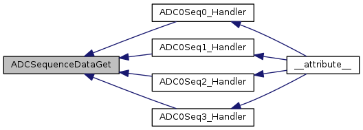
This function copies data from the specified sample sequencer output FIFO to a memory resident buffer. The number of samples available in the hardware FIFO are copied into the buffer, which is assumed to be large enough to hold that many samples. This function only returns the samples that are presently available, which may not be the entire sample sequence if it is in the process of being executed.

Returns
Returns the number of samples copied to the buffer.

Definition at line 824 of file adc.c.

References ADC0_BASE, ADC1_BASE, ADC_SEQ, ADC_SEQ_STEP, ADC_SSFIFO, ADC_SSFSTAT, ADC_SSFSTAT0_EMPTY, ASSERT, and HWREG.

Referenced by ADC0Seq0_Handler(), ADC0Seq1_Handler(), ADC0Seq2_Handler(), and ADC0Seq3_Handler().

826 {
827  uint32_t ui32Count;
828 
829  //
830  // Check the arguments.
831  //
832  ASSERT((ui32Base == ADC0_BASE) || (ui32Base == ADC1_BASE));
833  ASSERT(ui32SequenceNum < 4);
834 
835  //
836  // Get the offset of the sequence to be read.
837  //
838  ui32Base += ADC_SEQ + (ADC_SEQ_STEP * ui32SequenceNum);
839 
840  //
841  // Read samples from the FIFO until it is empty.
842  //
843  ui32Count = 0;
844  while(!(HWREG(ui32Base + ADC_SSFSTAT) & ADC_SSFSTAT0_EMPTY) &&
845  (ui32Count < 8))
846  {
847  //
848  // Read the FIFO and copy it to the destination.
849  //
850  *pui32Buffer++ = HWREG(ui32Base + ADC_SSFIFO);
851 
852  //
853  // Increment the count of samples read.
854  //
855  ui32Count++;
856  }
857 
858  //
859  // Return the number of samples read.
860  //
861  return(ui32Count);
862 }
#define HWREG(x)
Definition: hw_types.h:48
#define ADC1_BASE
Definition: hw_memmap.h:90
#define ASSERT(expr)
Definition: debug.h:67
#define ADC0_BASE
Definition: hw_memmap.h:89
#define ADC_SSFIFO
Definition: adc.c:69
#define ADC_SSFSTAT
Definition: adc.c:70
#define ADC_SSFSTAT0_EMPTY
Definition: hw_adc.h:505
#define ADC_SEQ
Definition: adc.c:64
#define ADC_SEQ_STEP
Definition: adc.c:65

Here is the caller graph for this function:

void ADCSequenceDisable ( uint32_t  ui32Base,
uint32_t  ui32SequenceNum 
)

Disables a sample sequence.

Parameters
ui32Baseis the base address of the ADC module.
ui32SequenceNumis the sample sequence number.

Prevents the specified sample sequence from being captured when its trigger is detected. A sample sequence must be disabled before it is configured.

Returns
None.

Definition at line 419 of file adc.c.

References ADC0_BASE, ADC1_BASE, ADC_O_ACTSS, ASSERT, and HWREG.

Referenced by adc_channel_init().

420 {
421  //
422  // Check the arguments.
423  //
424  ASSERT((ui32Base == ADC0_BASE) || (ui32Base == ADC1_BASE));
425  ASSERT(ui32SequenceNum < 4);
426 
427  //
428  // Disable the specified sequences.
429  //
430  HWREG(ui32Base + ADC_O_ACTSS) &= ~(1 << ui32SequenceNum);
431 }
#define HWREG(x)
Definition: hw_types.h:48
#define ADC1_BASE
Definition: hw_memmap.h:90
#define ASSERT(expr)
Definition: debug.h:67
#define ADC0_BASE
Definition: hw_memmap.h:89
#define ADC_O_ACTSS
Definition: hw_adc.h:48

Here is the caller graph for this function:

void ADCSequenceDMADisable ( uint32_t  ui32Base,
uint32_t  ui32SequenceNum 
)

Disables DMA for sample sequencers.

Parameters
ui32Baseis the base address of the ADC module.
ui32SequenceNumis the sample sequence number.

Prevents the specified sample sequencer from generating DMA requests.

Returns
None.

Definition at line 1799 of file adc.c.

References ADC0_BASE, ADC1_BASE, ADC_O_ACTSS, ASSERT, and HWREG.

1800 {
1801  //
1802  // Check the arguments.
1803  //
1804  ASSERT((ui32Base == ADC0_BASE) || (ui32Base == ADC1_BASE));
1805  ASSERT(ui32SequenceNum < 4);
1806 
1807  //
1808  // Disable the DMA on the specified sequencer.
1809  //
1810  HWREG(ui32Base + ADC_O_ACTSS) &= ~(0x100 << ui32SequenceNum);
1811 }
#define HWREG(x)
Definition: hw_types.h:48
#define ADC1_BASE
Definition: hw_memmap.h:90
#define ASSERT(expr)
Definition: debug.h:67
#define ADC0_BASE
Definition: hw_memmap.h:89
#define ADC_O_ACTSS
Definition: hw_adc.h:48
void ADCSequenceDMAEnable ( uint32_t  ui32Base,
uint32_t  ui32SequenceNum 
)

Enables DMA for sample sequencers.

Parameters
ui32Baseis the base address of the ADC module.
ui32SequenceNumis the sample sequence number.

Allows DMA requests to be generated based on the FIFO level of the sample sequencer.

Returns
None.

Definition at line 1772 of file adc.c.

References ADC0_BASE, ADC1_BASE, ADC_O_ACTSS, ASSERT, and HWREG.

1773 {
1774  //
1775  // Check the arguments.
1776  //
1777  ASSERT((ui32Base == ADC0_BASE) || (ui32Base == ADC1_BASE));
1778  ASSERT(ui32SequenceNum < 4);
1779 
1780  //
1781  // Enable the DMA on the specified sequencer.
1782  //
1783  HWREG(ui32Base + ADC_O_ACTSS) |= 0x100 << ui32SequenceNum;
1784 }
#define HWREG(x)
Definition: hw_types.h:48
#define ADC1_BASE
Definition: hw_memmap.h:90
#define ASSERT(expr)
Definition: debug.h:67
#define ADC0_BASE
Definition: hw_memmap.h:89
#define ADC_O_ACTSS
Definition: hw_adc.h:48
void ADCSequenceEnable ( uint32_t  ui32Base,
uint32_t  ui32SequenceNum 
)

Enables a sample sequence.

Parameters
ui32Baseis the base address of the ADC module.
ui32SequenceNumis the sample sequence number.

Allows the specified sample sequence to be captured when its trigger is detected. A sample sequence must be configured before it is enabled.

Returns
None.

Definition at line 391 of file adc.c.

References ADC0_BASE, ADC1_BASE, ADC_O_ACTSS, ASSERT, and HWREG.

Referenced by adc_channel_init().

392 {
393  //
394  // Check the arguments.
395  //
396  ASSERT((ui32Base == ADC0_BASE) || (ui32Base == ADC1_BASE));
397  ASSERT(ui32SequenceNum < 4);
398 
399  //
400  // Enable the specified sequence.
401  //
402  HWREG(ui32Base + ADC_O_ACTSS) |= 1 << ui32SequenceNum;
403 }
#define HWREG(x)
Definition: hw_types.h:48
#define ADC1_BASE
Definition: hw_memmap.h:90
#define ASSERT(expr)
Definition: debug.h:67
#define ADC0_BASE
Definition: hw_memmap.h:89
#define ADC_O_ACTSS
Definition: hw_adc.h:48

Here is the caller graph for this function:

int32_t ADCSequenceOverflow ( uint32_t  ui32Base,
uint32_t  ui32SequenceNum 
)

Determines if a sample sequence overflow occurred.

Parameters
ui32Baseis the base address of the ADC module.
ui32SequenceNumis the sample sequence number.

This function determines if a sample sequence overflow has occurred. Overflow happens if the captured samples are not read from the FIFO before the next trigger occurs.

Returns
Returns zero if there was not an overflow, and non-zero if there was.

Definition at line 704 of file adc.c.

References ADC0_BASE, ADC1_BASE, ADC_O_OSTAT, ASSERT, and HWREG.

705 {
706  //
707  // Check the arguments.
708  //
709  ASSERT((ui32Base == ADC0_BASE) || (ui32Base == ADC1_BASE));
710  ASSERT(ui32SequenceNum < 4);
711 
712  //
713  // Determine if there was an overflow on this sequence.
714  //
715  return(HWREG(ui32Base + ADC_O_OSTAT) & (1 << ui32SequenceNum));
716 }
#define ADC_O_OSTAT
Definition: hw_adc.h:52
#define HWREG(x)
Definition: hw_types.h:48
#define ADC1_BASE
Definition: hw_memmap.h:90
#define ASSERT(expr)
Definition: debug.h:67
#define ADC0_BASE
Definition: hw_memmap.h:89
void ADCSequenceOverflowClear ( uint32_t  ui32Base,
uint32_t  ui32SequenceNum 
)

Clears the overflow condition on a sample sequence.

Parameters
ui32Baseis the base address of the ADC module.
ui32SequenceNumis the sample sequence number.

This function clears an overflow condition on one of the sample sequences. The overflow condition must be cleared in order to detect a subsequent overflow condition (it otherwise causes no harm).

Returns
None.

Definition at line 733 of file adc.c.

References ADC0_BASE, ADC1_BASE, ADC_O_OSTAT, ASSERT, and HWREG.

734 {
735  //
736  // Check the arguments.
737  //
738  ASSERT((ui32Base == ADC0_BASE) || (ui32Base == ADC1_BASE));
739  ASSERT(ui32SequenceNum < 4);
740 
741  //
742  // Clear the overflow condition for this sequence.
743  //
744  HWREG(ui32Base + ADC_O_OSTAT) = 1 << ui32SequenceNum;
745 }
#define ADC_O_OSTAT
Definition: hw_adc.h:52
#define HWREG(x)
Definition: hw_types.h:48
#define ADC1_BASE
Definition: hw_memmap.h:90
#define ASSERT(expr)
Definition: debug.h:67
#define ADC0_BASE
Definition: hw_memmap.h:89
void ADCSequenceStepConfigure ( uint32_t  ui32Base,
uint32_t  ui32SequenceNum,
uint32_t  ui32Step,
uint32_t  ui32Config 
)

Configure a step of the sample sequencer.

Parameters
ui32Baseis the base address of the ADC module.
ui32SequenceNumis the sample sequence number.
ui32Stepis the step to be configured.
ui32Configis the configuration of this step; must be a logical OR of ADC_CTL_TS, ADC_CTL_IE, ADC_CTL_END, ADC_CTL_D, one of the input channel selects (ADC_CTL_CH0 through ADC_CTL_CH23), and one of the digital comparator selects (ADC_CTL_CMP0 through ADC_CTL_CMP7).

This function configures the ADC for one step of a sample sequence. The ADC can be configured for single-ended or differential operation (the ADC_CTL_D bit selects differential operation when set), the channel to be sampled can be chosen (the ADC_CTL_CH0 through ADC_CTL_CH23 values), and the internal temperature sensor can be selected (the ADC_CTL_TS bit). Additionally, this step can be defined as the last in the sequence (the ADC_CTL_END bit) and it can be configured to cause an interrupt when the step is complete (the ADC_CTL_IE bit). If the digital comparators are present on the device, this step may also be configured to send the ADC sample to the selected comparator using ADC_CTL_CMP0 through ADC_CTL_CMP7. The configuration is used by the ADC at the appropriate time when the trigger for this sequence occurs.

Note
If the Digital Comparator is present and enabled using the ADC_CTL_CMP0 through ADC_CTL_CMP7 selects, the ADC sample is NOT written into the ADC sequence data FIFO.

The ui32Step parameter determines the order in which the samples are captured by the ADC when the trigger occurs. It can range from zero to seven for the first sample sequencer, from zero to three for the second and third sample sequencer, and can only be zero for the fourth sample sequencer.

Differential mode only works with adjacent channel pairs (for example, 0 and 1). The channel select must be the number of the channel pair to sample (for example, ADC_CTL_CH0 for 0 and 1, or ADC_CTL_CH1 for 2 and 3) or undefined results are returned by the ADC. Additionally, if differential mode is selected when the temperature sensor is being sampled, undefined results are returned by the ADC.

It is the responsibility of the caller to ensure that a valid configuration is specified; this function does not check the validity of the specified configuration.

Returns
None.

Definition at line 605 of file adc.c.

References ADC0_BASE, ADC1_BASE, ADC_SEQ, ADC_SEQ_STEP, ADC_SSCTL, ADC_SSDC, ADC_SSEMUX, ADC_SSMUX, ADC_SSOP, ADC_SSTSH, ASSERT, and HWREG.

Referenced by adc_channel_init().

607 {
608  uint32_t ui32Temp;
609 
610  //
611  // Check the arguments.
612  //
613  ASSERT((ui32Base == ADC0_BASE) || (ui32Base == ADC1_BASE));
614  ASSERT(ui32SequenceNum < 4);
615  ASSERT(((ui32SequenceNum == 0) && (ui32Step < 8)) ||
616  ((ui32SequenceNum == 1) && (ui32Step < 4)) ||
617  ((ui32SequenceNum == 2) && (ui32Step < 4)) ||
618  ((ui32SequenceNum == 3) && (ui32Step < 1)));
619 
620  //
621  // Get the offset of the sequence to be configured.
622  //
623  ui32Base += ADC_SEQ + (ADC_SEQ_STEP * ui32SequenceNum);
624 
625  //
626  // Compute the shift for the bits that control this step.
627  //
628  ui32Step *= 4;
629 
630  //
631  // Set the analog mux value for this step.
632  //
633  HWREG(ui32Base + ADC_SSMUX) = ((HWREG(ui32Base + ADC_SSMUX) &
634  ~(0x0000000f << ui32Step)) |
635  ((ui32Config & 0x0f) << ui32Step));
636 
637  //
638  // Set the upper bits of the analog mux value for this step.
639  //
640  HWREG(ui32Base + ADC_SSEMUX) = ((HWREG(ui32Base + ADC_SSEMUX) &
641  ~(0x0000000f << ui32Step)) |
642  (((ui32Config & 0xf00) >> 8) << ui32Step));
643 
644  //
645  // Set the control value for this step.
646  //
647  HWREG(ui32Base + ADC_SSCTL) = ((HWREG(ui32Base + ADC_SSCTL) &
648  ~(0x0000000f << ui32Step)) |
649  (((ui32Config & 0xf0) >> 4) << ui32Step));
650 
651  //
652  // Set the sample and hold time for this step. This is not available on
653  // all devices, however on devices that do not support this feature these
654  // reserved bits are ignored on write access.
655  //
656  HWREG(ui32Base + ADC_SSTSH) = ((HWREG(ui32Base + ADC_SSTSH) &
657  ~(0x0000000f << ui32Step)) |
658  (((ui32Config & 0xf00000) >> 20) << ui32Step));
659 
660  //
661  // Enable digital comparator if specified in the ui32Config bit-fields.
662  //
663  if(ui32Config & 0x000F0000)
664  {
665  //
666  // Program the comparator for the specified step.
667  //
668  ui32Temp = HWREG(ui32Base + ADC_SSDC);
669  ui32Temp &= ~(0xF << ui32Step);
670  ui32Temp |= (((ui32Config & 0x00070000) >> 16) << ui32Step);
671  HWREG(ui32Base + ADC_SSDC) = ui32Temp;
672 
673  //
674  // Enable the comparator.
675  //
676  HWREG(ui32Base + ADC_SSOP) |= (1 << ui32Step);
677  }
678 
679  //
680  // Disable digital comparator if not specified.
681  //
682  else
683  {
684  HWREG(ui32Base + ADC_SSOP) &= ~(1 << ui32Step);
685  }
686 }
#define ADC_SSDC
Definition: adc.c:72
#define ADC_SSOP
Definition: adc.c:71
#define ADC_SSTSH
Definition: adc.c:73
#define ADC_SSCTL
Definition: adc.c:68
#define HWREG(x)
Definition: hw_types.h:48
#define ADC1_BASE
Definition: hw_memmap.h:90
#define ADC_SSMUX
Definition: adc.c:66
#define ASSERT(expr)
Definition: debug.h:67
#define ADC0_BASE
Definition: hw_memmap.h:89
#define ADC_SSEMUX
Definition: adc.c:67
#define ADC_SEQ
Definition: adc.c:64
#define ADC_SEQ_STEP
Definition: adc.c:65

Here is the caller graph for this function:

int32_t ADCSequenceUnderflow ( uint32_t  ui32Base,
uint32_t  ui32SequenceNum 
)

Determines if a sample sequence underflow occurred.

Parameters
ui32Baseis the base address of the ADC module.
ui32SequenceNumis the sample sequence number.

This function determines if a sample sequence underflow has occurred. Underflow happens if too many samples are read from the FIFO.

Returns
Returns zero if there was not an underflow, and non-zero if there was.

Definition at line 762 of file adc.c.

References ADC0_BASE, ADC1_BASE, ADC_O_USTAT, ASSERT, and HWREG.

763 {
764  //
765  // Check the arguments.
766  //
767  ASSERT((ui32Base == ADC0_BASE) || (ui32Base == ADC1_BASE));
768  ASSERT(ui32SequenceNum < 4);
769 
770  //
771  // Determine if there was an underflow on this sequence.
772  //
773  return(HWREG(ui32Base + ADC_O_USTAT) & (1 << ui32SequenceNum));
774 }
#define HWREG(x)
Definition: hw_types.h:48
#define ADC1_BASE
Definition: hw_memmap.h:90
#define ASSERT(expr)
Definition: debug.h:67
#define ADC0_BASE
Definition: hw_memmap.h:89
#define ADC_O_USTAT
Definition: hw_adc.h:54
void ADCSequenceUnderflowClear ( uint32_t  ui32Base,
uint32_t  ui32SequenceNum 
)

Clears the underflow condition on a sample sequence.

Parameters
ui32Baseis the base address of the ADC module.
ui32SequenceNumis the sample sequence number.

This function clears an underflow condition on one of the sample sequencers. The underflow condition must be cleared in order to detect a subsequent underflow condition (it otherwise causes no harm).

Returns
None.

Definition at line 791 of file adc.c.

References ADC0_BASE, ADC1_BASE, ADC_O_USTAT, ASSERT, and HWREG.

792 {
793  //
794  // Check the arguments.
795  //
796  ASSERT((ui32Base == ADC0_BASE) || (ui32Base == ADC1_BASE));
797  ASSERT(ui32SequenceNum < 4);
798 
799  //
800  // Clear the underflow condition for this sequence.
801  //
802  HWREG(ui32Base + ADC_O_USTAT) = 1 << ui32SequenceNum;
803 }
#define HWREG(x)
Definition: hw_types.h:48
#define ADC1_BASE
Definition: hw_memmap.h:90
#define ASSERT(expr)
Definition: debug.h:67
#define ADC0_BASE
Definition: hw_memmap.h:89
#define ADC_O_USTAT
Definition: hw_adc.h:54
void ADCSoftwareOversampleConfigure ( uint32_t  ui32Base,
uint32_t  ui32SequenceNum,
uint32_t  ui32Factor 
)

Configures the software oversampling factor of the ADC.

Parameters
ui32Baseis the base address of the ADC module.
ui32SequenceNumis the sample sequence number.
ui32Factoris the number of samples to be averaged.

This function configures the software oversampling for the ADC, which can be used to provide better resolution on the sampled data. Oversampling is accomplished by averaging multiple samples from the same analog input. Three different oversampling rates are supported; 2x, 4x, and 8x.

Oversampling is only supported on the sample sequencers that are more than one sample in depth (that is, the fourth sample sequencer is not supported). Oversampling by 2x (for example) divides the depth of the sample sequencer by two; so 2x oversampling on the first sample sequencer can only provide four samples per trigger. This also means that 8x oversampling is only available on the first sample sequencer.

Returns
None.

Definition at line 923 of file adc.c.

References ADC0_BASE, ADC1_BASE, ASSERT, and g_pui8OversampleFactor.

925 {
926  uint32_t ui32Value;
927 
928  //
929  // Check the arguments.
930  //
931  ASSERT((ui32Base == ADC0_BASE) || (ui32Base == ADC1_BASE));
932  ASSERT(ui32SequenceNum < 3);
933  ASSERT(((ui32Factor == 2) || (ui32Factor == 4) || (ui32Factor == 8)) &&
934  ((ui32SequenceNum == 0) || (ui32Factor != 8)));
935 
936  //
937  // Convert the oversampling factor to a shift factor.
938  //
939  for(ui32Value = 0, ui32Factor >>= 1; ui32Factor;
940  ui32Value++, ui32Factor >>= 1)
941  {
942  }
943 
944  //
945  // Save the shift factor.
946  //
947  g_pui8OversampleFactor[ui32SequenceNum] = ui32Value;
948 }
#define ADC1_BASE
Definition: hw_memmap.h:90
#define ASSERT(expr)
Definition: debug.h:67
#define ADC0_BASE
Definition: hw_memmap.h:89
static uint8_t g_pui8OversampleFactor[3]
Definition: adc.c:81
void ADCSoftwareOversampleDataGet ( uint32_t  ui32Base,
uint32_t  ui32SequenceNum,
uint32_t *  pui32Buffer,
uint32_t  ui32Count 
)

Gets the captured data for a sample sequence using software oversampling.

Parameters
ui32Baseis the base address of the ADC module.
ui32SequenceNumis the sample sequence number.
pui32Bufferis the address where the data is stored.
ui32Countis the number of samples to be read.

This function copies data from the specified sample sequence output FIFO to a memory resident buffer with software oversampling applied. The requested number of samples are copied into the data buffer; if there are not enough samples in the hardware FIFO to satisfy this many oversampled data items, then incorrect results are returned. It is the caller's responsibility to read only the samples that are available and wait until enough data is available, for example as a result of receiving an interrupt.

Returns
None.

Definition at line 1053 of file adc.c.

References ADC0_BASE, ADC1_BASE, ADC_SEQ, ADC_SEQ_STEP, ADC_SSFIFO, ASSERT, g_pui8OversampleFactor, and HWREG.

1055 {
1056  uint32_t ui32Idx, ui32Accum;
1057 
1058  //
1059  // Check the arguments.
1060  //
1061  ASSERT((ui32Base == ADC0_BASE) || (ui32Base == ADC1_BASE));
1062  ASSERT(ui32SequenceNum < 3);
1063  ASSERT(((ui32SequenceNum == 0) &&
1064  (ui32Count < (8 >> g_pui8OversampleFactor[ui32SequenceNum]))) ||
1065  (ui32Count < (4 >> g_pui8OversampleFactor[ui32SequenceNum])));
1066 
1067  //
1068  // Get the offset of the sequence to be read.
1069  //
1070  ui32Base += ADC_SEQ + (ADC_SEQ_STEP * ui32SequenceNum);
1071 
1072  //
1073  // Read the samples from the FIFO until it is empty.
1074  //
1075  while(ui32Count--)
1076  {
1077  //
1078  // Compute the sum of the samples.
1079  //
1080  ui32Accum = 0;
1081  for(ui32Idx = 1 << g_pui8OversampleFactor[ui32SequenceNum]; ui32Idx;
1082  ui32Idx--)
1083  {
1084  //
1085  // Read the FIFO and add it to the accumulator.
1086  //
1087  ui32Accum += HWREG(ui32Base + ADC_SSFIFO);
1088  }
1089 
1090  //
1091  // Write the averaged sample to the output buffer.
1092  //
1093  *pui32Buffer++ = ui32Accum >> g_pui8OversampleFactor[ui32SequenceNum];
1094  }
1095 }
#define HWREG(x)
Definition: hw_types.h:48
#define ADC1_BASE
Definition: hw_memmap.h:90
#define ASSERT(expr)
Definition: debug.h:67
#define ADC0_BASE
Definition: hw_memmap.h:89
#define ADC_SSFIFO
Definition: adc.c:69
static uint8_t g_pui8OversampleFactor[3]
Definition: adc.c:81
#define ADC_SEQ
Definition: adc.c:64
#define ADC_SEQ_STEP
Definition: adc.c:65
void ADCSoftwareOversampleStepConfigure ( uint32_t  ui32Base,
uint32_t  ui32SequenceNum,
uint32_t  ui32Step,
uint32_t  ui32Config 
)

Configures a step of the software oversampled sequencer.

Parameters
ui32Baseis the base address of the ADC module.
ui32SequenceNumis the sample sequence number.
ui32Stepis the step to be configured.
ui32Configis the configuration of this step.

This function configures a step of the sample sequencer when using the software oversampling feature. The number of steps available depends on the oversampling factor set by ADCSoftwareOversampleConfigure(). The value of ui32Config is the same as defined for ADCSequenceStepConfigure().

Returns
None.

Definition at line 968 of file adc.c.

References ADC0_BASE, ADC1_BASE, ADC_SEQ, ADC_SEQ_STEP, ADC_SSCTL, ADC_SSCTL0_END0, ADC_SSCTL0_IE0, ADC_SSEMUX, ADC_SSMUX, ASSERT, g_pui8OversampleFactor, and HWREG.

970 {
971  //
972  // Check the arguments.
973  //
974  ASSERT((ui32Base == ADC0_BASE) || (ui32Base == ADC1_BASE));
975  ASSERT(ui32SequenceNum < 3);
976  ASSERT(((ui32SequenceNum == 0) &&
977  (ui32Step < (8 >> g_pui8OversampleFactor[ui32SequenceNum]))) ||
978  (ui32Step < (4 >> g_pui8OversampleFactor[ui32SequenceNum])));
979 
980  //
981  // Get the offset of the sequence to be configured.
982  //
983  ui32Base += ADC_SEQ + (ADC_SEQ_STEP * ui32SequenceNum);
984 
985  //
986  // Compute the shift for the bits that control this step.
987  //
988  ui32Step *= 4 << g_pui8OversampleFactor[ui32SequenceNum];
989 
990  //
991  // Loop through the hardware steps that make up this step of the software
992  // oversampled sequence.
993  //
994  for(ui32SequenceNum = 1 << g_pui8OversampleFactor[ui32SequenceNum];
995  ui32SequenceNum; ui32SequenceNum--)
996  {
997  //
998  // Set the analog mux value for this step.
999  //
1000  HWREG(ui32Base + ADC_SSMUX) = ((HWREG(ui32Base + ADC_SSMUX) &
1001  ~(0x0000000f << ui32Step)) |
1002  ((ui32Config & 0x0f) << ui32Step));
1003 
1004  //
1005  // Set the upper bits of the analog mux value for this step.
1006  //
1007  HWREG(ui32Base + ADC_SSEMUX) = ((HWREG(ui32Base + ADC_SSEMUX) &
1008  ~(0x0000000f << ui32Step)) |
1009  (((ui32Config & 0xf00) >> 8) <<
1010  ui32Step));
1011 
1012  //
1013  // Set the control value for this step.
1014  //
1015  HWREG(ui32Base + ADC_SSCTL) = ((HWREG(ui32Base + ADC_SSCTL) &
1016  ~(0x0000000f << ui32Step)) |
1017  (((ui32Config & 0xf0) >> 4) <<
1018  ui32Step));
1019  if(ui32SequenceNum != 1)
1020  {
1021  HWREG(ui32Base + ADC_SSCTL) &= ~((ADC_SSCTL0_IE0 |
1022  ADC_SSCTL0_END0) << ui32Step);
1023  }
1024 
1025  //
1026  // Go to the next hardware step.
1027  //
1028  ui32Step += 4;
1029  }
1030 }
#define ADC_SSCTL
Definition: adc.c:68
#define HWREG(x)
Definition: hw_types.h:48
#define ADC1_BASE
Definition: hw_memmap.h:90
#define ADC_SSMUX
Definition: adc.c:66
#define ADC_SSCTL0_IE0
Definition: hw_adc.h:486
#define ASSERT(expr)
Definition: debug.h:67
#define ADC_SSCTL0_END0
Definition: hw_adc.h:487
#define ADC0_BASE
Definition: hw_memmap.h:89
#define ADC_SSEMUX
Definition: adc.c:67
static uint8_t g_pui8OversampleFactor[3]
Definition: adc.c:81
#define ADC_SEQ
Definition: adc.c:64
#define ADC_SEQ_STEP
Definition: adc.c:65

Variable Documentation

uint8_t g_pui8OversampleFactor[3]
static