|
EE445M RTOS
Taken at the University of Texas Spring 2015
|
|
EE445M RTOS
Taken at the University of Texas Spring 2015
|
Functions | |
| static uint32_t | _GPIOIntNumberGet (uint32_t ui32Port) |
| void | GPIODirModeSet (uint32_t ui32Port, uint8_t ui8Pins, uint32_t ui32PinIO) |
| uint32_t | GPIODirModeGet (uint32_t ui32Port, uint8_t ui8Pin) |
| void | GPIOIntTypeSet (uint32_t ui32Port, uint8_t ui8Pins, uint32_t ui32IntType) |
| uint32_t | GPIOIntTypeGet (uint32_t ui32Port, uint8_t ui8Pin) |
| void | GPIOPadConfigSet (uint32_t ui32Port, uint8_t ui8Pins, uint32_t ui32Strength, uint32_t ui32PinType) |
| void | GPIOPadConfigGet (uint32_t ui32Port, uint8_t ui8Pin, uint32_t *pui32Strength, uint32_t *pui32PinType) |
| void | GPIOIntEnable (uint32_t ui32Port, uint32_t ui32IntFlags) |
| void | GPIOIntDisable (uint32_t ui32Port, uint32_t ui32IntFlags) |
| uint32_t | GPIOIntStatus (uint32_t ui32Port, bool bMasked) |
| void | GPIOIntClear (uint32_t ui32Port, uint32_t ui32IntFlags) |
| void | GPIOIntRegister (uint32_t ui32Port, void(*pfnIntHandler)(void)) |
| void | GPIOIntUnregister (uint32_t ui32Port) |
| int32_t | GPIOPinRead (uint32_t ui32Port, uint8_t ui8Pins) |
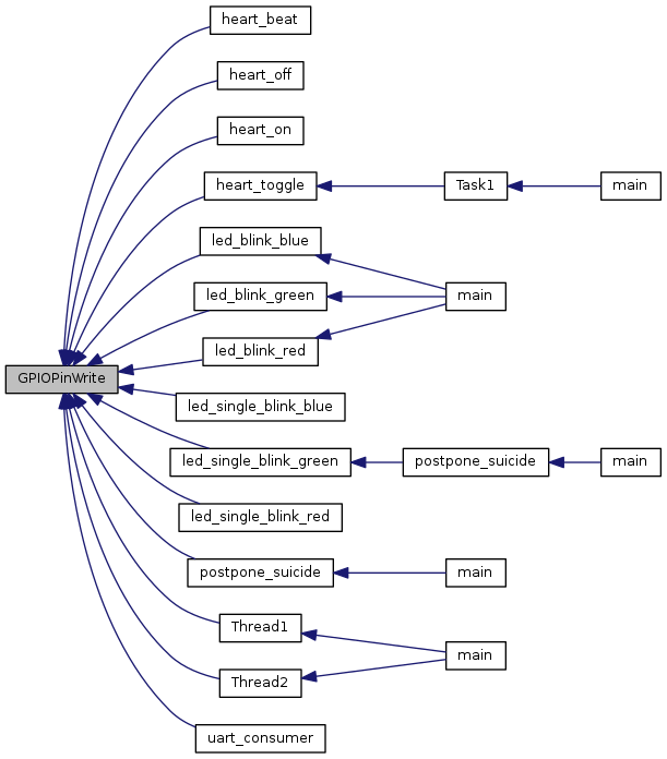
| void | GPIOPinWrite (uint32_t ui32Port, uint8_t ui8Pins, uint8_t ui8Val) |
| void | GPIOPinTypeADC (uint32_t ui32Port, uint8_t ui8Pins) |
| void | GPIOPinTypeCAN (uint32_t ui32Port, uint8_t ui8Pins) |
| void | GPIOPinTypeComparator (uint32_t ui32Port, uint8_t ui8Pins) |
| void | GPIOPinTypeEPI (uint32_t ui32Port, uint8_t ui8Pins) |
| void | GPIOPinTypeEthernetLED (uint32_t ui32Port, uint8_t ui8Pins) |
| void | GPIOPinTypeEthernetMII (uint32_t ui32Port, uint8_t ui8Pins) |
| void | GPIOPinTypeGPIOInput (uint32_t ui32Port, uint8_t ui8Pins) |
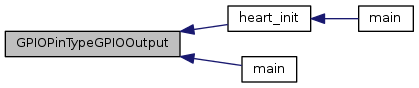
| void | GPIOPinTypeGPIOOutput (uint32_t ui32Port, uint8_t ui8Pins) |
| void | GPIOPinTypeGPIOOutputOD (uint32_t ui32Port, uint8_t ui8Pins) |
| void | GPIOPinTypeI2C (uint32_t ui32Port, uint8_t ui8Pins) |
| void | GPIOPinTypeI2CSCL (uint32_t ui32Port, uint8_t ui8Pins) |
| void | GPIOPinTypeLCD (uint32_t ui32Port, uint8_t ui8Pins) |
| void | GPIOPinTypeLPC (uint32_t ui32Port, uint8_t ui8Pins) |
| void | GPIOPinTypePECIRx (uint32_t ui32Port, uint8_t ui8Pins) |
| void | GPIOPinTypePECITx (uint32_t ui32Port, uint8_t ui8Pins) |
| void | GPIOPinTypePWM (uint32_t ui32Port, uint8_t ui8Pins) |
| void | GPIOPinTypeQEI (uint32_t ui32Port, uint8_t ui8Pins) |
| void | GPIOPinTypeSSI (uint32_t ui32Port, uint8_t ui8Pins) |
| void | GPIOPinTypeTimer (uint32_t ui32Port, uint8_t ui8Pins) |
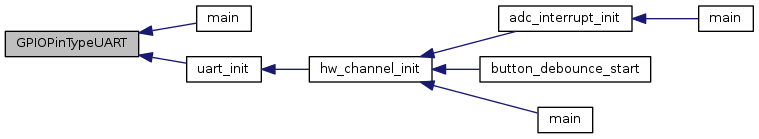
| void | GPIOPinTypeUART (uint32_t ui32Port, uint8_t ui8Pins) |
| void | GPIOPinTypeUSBAnalog (uint32_t ui32Port, uint8_t ui8Pins) |
| void | GPIOPinTypeUSBDigital (uint32_t ui32Port, uint8_t ui8Pins) |
| void | GPIOPinTypeWakeHigh (uint32_t ui32Port, uint8_t ui8Pins) |
| void | GPIOPinTypeWakeLow (uint32_t ui32Port, uint8_t ui8Pins) |
| void | GPIOPinTypeKBRow (uint32_t ui32Port, uint8_t ui8Pins) |
| void | GPIOPinTypeKBColumn (uint32_t ui32Port, uint8_t ui8Pins) |
| void | GPIOPinTypeLEDSeq (uint32_t ui32Port, uint8_t ui8Pins) |
| void | GPIOPinTypeCIR (uint32_t ui32Port, uint8_t ui8Pins) |
| uint32_t | GPIOPinWakeStatus (uint32_t ui32Port) |
| void | GPIOPinConfigure (uint32_t ui32PinConfig) |
| void | GPIODMATriggerEnable (uint32_t ui32Port, uint8_t ui8Pins) |
| void | GPIODMATriggerDisable (uint32_t ui32Port, uint8_t ui8Pins) |
| void | GPIOADCTriggerEnable (uint32_t ui32Port, uint8_t ui8Pins) |
| void | GPIOADCTriggerDisable (uint32_t ui32Port, uint8_t ui8Pins) |
Variables | |
| static const uint32_t | g_ppui32GPIOIntMapBlizzard [][2] |
| static const uint_fast32_t | g_ui32GPIOIntMapBlizzardRows |
| static const uint32_t | g_ppui32GPIOIntMapSnowflake [][2] |
| static const uint_fast32_t | g_ui32GPIOIntMapSnowflakeRows |
| static const uint32_t | g_pui32GPIOBaseAddrs [] |
|
static |
Gets the GPIO interrupt number.
| ui32Port | is the base address of the GPIO port. |
Given a GPIO base address, this function returns the corresponding interrupt number.
Definition at line 212 of file gpio.c.
References ASSERT, CLASS_IS_TM4C129, g_ppui32GPIOIntMapBlizzard, g_ppui32GPIOIntMapSnowflake, g_ui32GPIOIntMapBlizzardRows, and g_ui32GPIOIntMapSnowflakeRows.
Referenced by GPIOIntRegister(), and GPIOIntUnregister().

| void GPIOADCTriggerDisable | ( | uint32_t | ui32Port, |
| uint8_t | ui8Pins | ||
| ) |
Disable a GPIO pin as a trigger to start an ADC capture.
| ui32Port | is the base address of the GPIO port. |
| ui8Pins | is the bit-packed representation of the pin(s). |
This function disables a GPIO pin to be used as a trigger to start an ADC sequence. This function can be used to disable this feature if it was enabled via a call to GPIOADCTriggerEnable().
Definition at line 2653 of file gpio.c.
References ASSERT, GPIO_O_ADCCTL, and HWREG.
| void GPIOADCTriggerEnable | ( | uint32_t | ui32Port, |
| uint8_t | ui8Pins | ||
| ) |
Enables a GPIO pin as a trigger to start an ADC capture.
| ui32Port | is the base address of the GPIO port. |
| ui8Pins | is the bit-packed representation of the pin(s). |
This function enables a GPIO pin to be used as a trigger to start an ADC sequence. Any GPIO pin can be configured to be an external trigger for an ADC sequence. The GPIO pin still generates interrupts if the interrupt is enabled for the selected pin. To enable the use of a GPIO pin to trigger the ADC module, the ADCSequenceConfigure() function must be called with the ADC_TRIGGER_EXTERNAL parameter.
Definition at line 2625 of file gpio.c.
References ASSERT, GPIO_O_ADCCTL, and HWREG.
| uint32_t GPIODirModeGet | ( | uint32_t | ui32Port, |
| uint8_t | ui8Pin | ||
| ) |
Gets the direction and mode of a pin.
| ui32Port | is the base address of the GPIO port. |
| ui8Pin | is the pin number. |
This function gets the direction and control mode for a specified pin on the selected GPIO port. The pin can be configured as either an input or output under software control, or it can be under hardware control. The type of control and direction are returned as an enumerated data type.
Definition at line 338 of file gpio.c.
References ASSERT, GPIO_O_AFSEL, GPIO_O_DIR, and HWREG.
| void GPIODirModeSet | ( | uint32_t | ui32Port, |
| uint8_t | ui8Pins, | ||
| uint32_t | ui32PinIO | ||
| ) |
Sets the direction and mode of the specified pin(s).
| ui32Port | is the base address of the GPIO port |
| ui8Pins | is the bit-packed representation of the pin(s). |
| ui32PinIO | is the pin direction and/or mode. |
This function configures the specified pin(s) on the selected GPIO port as either input or output under software control, or it configures the pin to be under hardware control.
The parameter ui32PinIO is an enumerated data type that can be one of the following values:
where GPIO_DIR_MODE_IN specifies that the pin is programmed as a software controlled input, GPIO_DIR_MODE_OUT specifies that the pin is programmed as a software controlled output, and GPIO_DIR_MODE_HW specifies that the pin is placed under hardware control.
The pin(s) are specified using a bit-packed byte, where each bit that is set identifies the pin to be accessed, and where bit 0 of the byte represents GPIO port pin 0, bit 1 represents GPIO port pin 1, and so on.
Definition at line 298 of file gpio.c.
References ASSERT, GPIO_DIR_MODE_HW, GPIO_DIR_MODE_IN, GPIO_DIR_MODE_OUT, GPIO_O_AFSEL, GPIO_O_DIR, and HWREG.
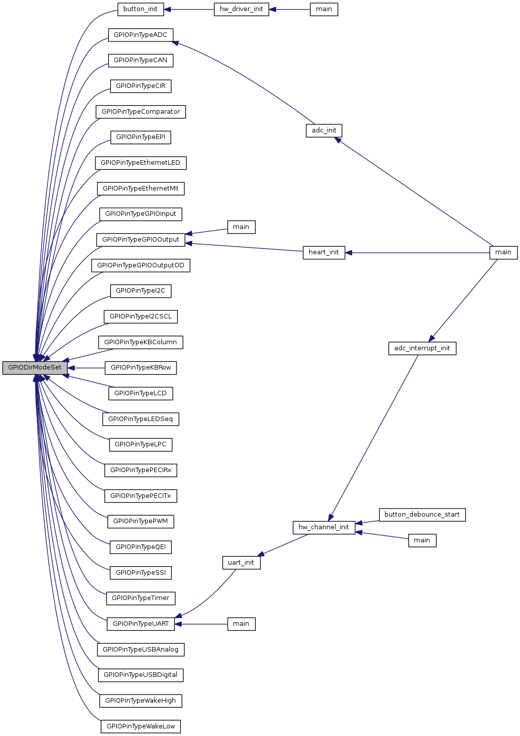
Referenced by button_init(), GPIOPinTypeADC(), GPIOPinTypeCAN(), GPIOPinTypeCIR(), GPIOPinTypeComparator(), GPIOPinTypeEPI(), GPIOPinTypeEthernetLED(), GPIOPinTypeEthernetMII(), GPIOPinTypeGPIOInput(), GPIOPinTypeGPIOOutput(), GPIOPinTypeGPIOOutputOD(), GPIOPinTypeI2C(), GPIOPinTypeI2CSCL(), GPIOPinTypeKBColumn(), GPIOPinTypeKBRow(), GPIOPinTypeLCD(), GPIOPinTypeLEDSeq(), GPIOPinTypeLPC(), GPIOPinTypePECIRx(), GPIOPinTypePECITx(), GPIOPinTypePWM(), GPIOPinTypeQEI(), GPIOPinTypeSSI(), GPIOPinTypeTimer(), GPIOPinTypeUART(), GPIOPinTypeUSBAnalog(), GPIOPinTypeUSBDigital(), GPIOPinTypeWakeHigh(), and GPIOPinTypeWakeLow().
| void GPIODMATriggerDisable | ( | uint32_t | ui32Port, |
| uint8_t | ui8Pins | ||
| ) |
Disables a GPIO pin as a trigger to start a DMA transaction.
| ui32Port | is the base address of the GPIO port. |
| ui8Pins | is the bit-packed representation of the pin(s). |
This function disables a GPIO pin from being used as a trigger to start a uDMA transaction. This function can be used to disable this feature if it was enabled via a call to GPIODMATriggerEnable().
Definition at line 2594 of file gpio.c.
References ASSERT, GPIO_O_DMACTL, and HWREG.
| void GPIODMATriggerEnable | ( | uint32_t | ui32Port, |
| uint8_t | ui8Pins | ||
| ) |
Enables a GPIO pin as a trigger to start a DMA transaction.
| ui32Port | is the base address of the GPIO port. |
| ui8Pins | is the bit-packed representation of the pin(s). |
This function enables a GPIO pin to be used as a trigger to start a uDMA transaction. Any GPIO pin can be configured to be an external trigger for the uDMA. The GPIO pin still generates interrupts if the interrupt is enabled for the selected pin.
Definition at line 2566 of file gpio.c.
References ASSERT, GPIO_O_DMACTL, and HWREG.
| void GPIOIntClear | ( | uint32_t | ui32Port, |
| uint32_t | ui32IntFlags | ||
| ) |
Clears the specified interrupt sources.
| ui32Port | is the base address of the GPIO port. |
| ui32IntFlags | is the bit mask of the interrupt sources to disable. |
Clears the interrupt for the specified interrupt source(s).
The ui32IntFlags parameter is the logical OR of the GPIO_INT_* values.
Definition at line 878 of file gpio.c.
References ASSERT, GPIO_O_ICR, and HWREG.
Referenced by GPIOPortF_Handler().

| void GPIOIntDisable | ( | uint32_t | ui32Port, |
| uint32_t | ui32IntFlags | ||
| ) |
Disables the specified GPIO interrupts.
| ui32Port | is the base address of the GPIO port. |
| ui32IntFlags | is the bit mask of the interrupt sources to disable. |
This function disables the indicated GPIO interrupt sources. Only the sources that are enabled can be reflected to the processor interrupt; disabled sources have no effect on the processor.
The ui32IntFlags parameter is the logical OR of any of the following:
Definition at line 803 of file gpio.c.
References ASSERT, GPIO_O_IM, and HWREG.
| void GPIOIntEnable | ( | uint32_t | ui32Port, |
| uint32_t | ui32IntFlags | ||
| ) |
Enables the specified GPIO interrupts.
| ui32Port | is the base address of the GPIO port. |
| ui32IntFlags | is the bit mask of the interrupt sources to enable. |
This function enables the indicated GPIO interrupt sources. Only the sources that are enabled can be reflected to the processor interrupt; disabled sources have no effect on the processor.
The ui32IntFlags parameter is the logical OR of any of the following:
Definition at line 763 of file gpio.c.
References ASSERT, GPIO_O_IM, and HWREG.
Referenced by button_init().

| void GPIOIntRegister | ( | uint32_t | ui32Port, |
| void(*)(void) | pfnIntHandler | ||
| ) |
Registers an interrupt handler for a GPIO port.
| ui32Port | is the base address of the GPIO port. |
| pfnIntHandler | is a pointer to the GPIO port interrupt handling function. |
This function ensures that the interrupt handler specified by pfnIntHandler is called when an interrupt is detected from the selected GPIO port. This function also enables the corresponding GPIO interrupt in the interrupt controller; individual pin interrupts and interrupt sources must be enabled with GPIOIntEnable().
Definition at line 912 of file gpio.c.
References _GPIOIntNumberGet(), ASSERT, IntEnable(), and IntRegister().

| uint32_t GPIOIntStatus | ( | uint32_t | ui32Port, |
| bool | bMasked | ||
| ) |
Gets interrupt status for the specified GPIO port.
| ui32Port | is the base address of the GPIO port. |
| bMasked | specifies whether masked or raw interrupt status is returned. |
If bMasked is set as true, then the masked interrupt status is returned; otherwise, the raw interrupt status is returned.
Definition at line 833 of file gpio.c.
References ASSERT, GPIO_O_MIS, GPIO_O_RIS, and HWREG.
| uint32_t GPIOIntTypeGet | ( | uint32_t | ui32Port, |
| uint8_t | ui8Pin | ||
| ) |
Gets the interrupt type for a pin.
| ui32Port | is the base address of the GPIO port. |
| ui8Pin | is the pin number. |
This function gets the interrupt type for a specified pin on the selected GPIO port. The pin can be configured as a falling-edge, rising-edge, or both-edges detected interrupt, or it can be configured as a low-level or high-level detected interrupt. The type of interrupt detection mechanism is returned and can include the GPIO_DISCRETE_INT flag.
Definition at line 454 of file gpio.c.
References ASSERT, GPIO_O_IBE, GPIO_O_IEV, GPIO_O_IS, GPIO_O_SI, and HWREG.
| void GPIOIntTypeSet | ( | uint32_t | ui32Port, |
| uint8_t | ui8Pins, | ||
| uint32_t | ui32IntType | ||
| ) |
Sets the interrupt type for the specified pin(s).
| ui32Port | is the base address of the GPIO port. |
| ui8Pins | is the bit-packed representation of the pin(s). |
| ui32IntType | specifies the type of interrupt trigger mechanism. |
This function sets up the various interrupt trigger mechanisms for the specified pin(s) on the selected GPIO port.
One of the following flags can be used to define the ui32IntType parameter:
In addition to the above flags, the following flag can be OR'd in to the ui32IntType parameter:
The GPIO_DISCRETE_INT is not available on all devices or all GPIO ports, consult the data sheet to ensure that the device and the GPIO port supports discrete interrupts.
The pin(s) are specified using a bit-packed byte, where each bit that is set identifies the pin to be accessed, and where bit 0 of the byte represents GPIO port pin 0, bit 1 represents GPIO port pin 1, and so on.
Definition at line 402 of file gpio.c.
References ASSERT, GPIO_BOTH_EDGES, GPIO_FALLING_EDGE, GPIO_HIGH_LEVEL, GPIO_LOW_LEVEL, GPIO_O_IBE, GPIO_O_IEV, GPIO_O_IS, GPIO_O_SI, GPIO_RISING_EDGE, and HWREG.
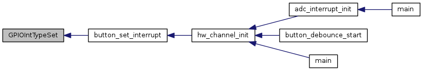
Referenced by button_set_interrupt().
| void GPIOIntUnregister | ( | uint32_t | ui32Port | ) |
Removes an interrupt handler for a GPIO port.
| ui32Port | is the base address of the GPIO port. |
This function unregisters the interrupt handler for the specified GPIO port. This function also disables the corresponding GPIO port interrupt in the interrupt controller; individual GPIO interrupts and interrupt sources must be disabled with GPIOIntDisable().
Definition at line 957 of file gpio.c.
References _GPIOIntNumberGet(), ASSERT, IntDisable(), and IntUnregister().

| void GPIOPadConfigGet | ( | uint32_t | ui32Port, |
| uint8_t | ui8Pin, | ||
| uint32_t * | pui32Strength, | ||
| uint32_t * | pui32PinType | ||
| ) |
Gets the pad configuration for a pin.
| ui32Port | is the base address of the GPIO port. |
| ui8Pin | is the pin number. |
| pui32Strength | is a pointer to storage for the output drive strength. |
| pui32PinType | is a pointer to storage for the output drive type. |
This function gets the pad configuration for a specified pin on the selected GPIO port. The values returned in pui32Strength and pui32PinType correspond to the values used in GPIOPadConfigSet(). This function also works for pin(s) configured as input pin(s); however, the only meaningful data returned is whether the pin is terminated with a pull-up or down resistor.
Definition at line 684 of file gpio.c.
References ASSERT, GPIO_O_DEN, GPIO_O_DR12R, GPIO_O_DR2R, GPIO_O_DR4R, GPIO_O_DR8R, GPIO_O_ODR, GPIO_O_PC, GPIO_O_PDR, GPIO_O_PUR, GPIO_O_SLR, GPIO_O_WAKELVL, GPIO_O_WAKEPEN, and HWREG.
| void GPIOPadConfigSet | ( | uint32_t | ui32Port, |
| uint8_t | ui8Pins, | ||
| uint32_t | ui32Strength, | ||
| uint32_t | ui32PinType | ||
| ) |
Sets the pad configuration for the specified pin(s).
| ui32Port | is the base address of the GPIO port. |
| ui8Pins | is the bit-packed representation of the pin(s). |
| ui32Strength | specifies the output drive strength. |
| ui32PinType | specifies the pin type. |
This function sets the drive strength and type for the specified pin(s) on the selected GPIO port. For pin(s) configured as input ports, the pad is configured as requested, but the only real effect on the input is the configuration of the pull-up or pull-down termination.
The parameter ui32Strength can be one of the following values:
where GPIO_STRENGTH_xMA specifies either 2, 4, or 8 mA output drive strength, and GPIO_OUT_STRENGTH_8MA_SC specifies 8 mA output drive with slew control.
Some Tiva devices also support output drive strengths of 6, 10, and 12 mA.
The parameter ui32PinType can be one of the following values:
where GPIO_PIN_TYPE_STD* specifies a push-pull pin, GPIO_PIN_TYPE_OD* specifies an open-drain pin, *_WPU specifies a weak pull-up, *_WPD specifies a weak pull-down, and GPIO_PIN_TYPE_ANALOG specifies an analog input.
The GPIO_PIN_TYPE_WAKE_* settings specify the pin to be used as a hibernation wake source. The pin sense level can be high or low. These settings are only available on some Tiva devices.
The pin(s) are specified using a bit-packed byte, where each bit that is set identifies the pin to be accessed, and where bit 0 of the byte represents GPIO port pin 0, bit 1 represents GPIO port pin 1, and so on.
Definition at line 546 of file gpio.c.
References ASSERT, GPIO_O_AMSEL, GPIO_O_DEN, GPIO_O_DR12R, GPIO_O_DR2R, GPIO_O_DR4R, GPIO_O_DR8R, GPIO_O_ODR, GPIO_O_PC, GPIO_O_PDR, GPIO_O_PUR, GPIO_O_SLR, GPIO_O_WAKELVL, GPIO_O_WAKEPEN, GPIO_PIN_TYPE_ANALOG, GPIO_PIN_TYPE_OD, GPIO_PIN_TYPE_STD, GPIO_PIN_TYPE_STD_WPD, GPIO_PIN_TYPE_STD_WPU, GPIO_PIN_TYPE_WAKE_HIGH, GPIO_PIN_TYPE_WAKE_LOW, GPIO_STRENGTH_10MA, GPIO_STRENGTH_12MA, GPIO_STRENGTH_2MA, GPIO_STRENGTH_4MA, GPIO_STRENGTH_6MA, GPIO_STRENGTH_8MA, GPIO_STRENGTH_8MA_SC, and HWREG.
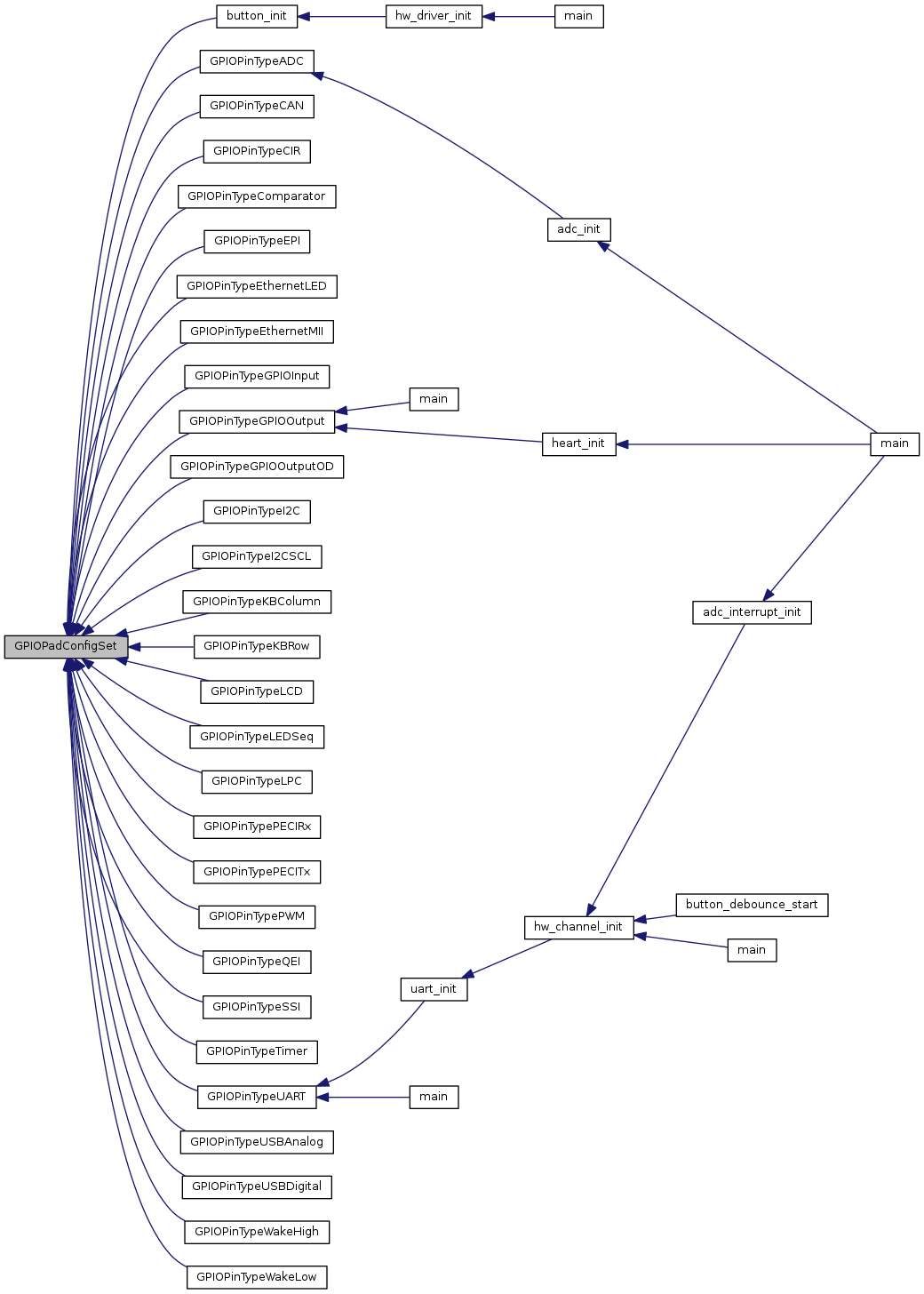
Referenced by button_init(), GPIOPinTypeADC(), GPIOPinTypeCAN(), GPIOPinTypeCIR(), GPIOPinTypeComparator(), GPIOPinTypeEPI(), GPIOPinTypeEthernetLED(), GPIOPinTypeEthernetMII(), GPIOPinTypeGPIOInput(), GPIOPinTypeGPIOOutput(), GPIOPinTypeGPIOOutputOD(), GPIOPinTypeI2C(), GPIOPinTypeI2CSCL(), GPIOPinTypeKBColumn(), GPIOPinTypeKBRow(), GPIOPinTypeLCD(), GPIOPinTypeLEDSeq(), GPIOPinTypeLPC(), GPIOPinTypePECIRx(), GPIOPinTypePECITx(), GPIOPinTypePWM(), GPIOPinTypeQEI(), GPIOPinTypeSSI(), GPIOPinTypeTimer(), GPIOPinTypeUART(), GPIOPinTypeUSBAnalog(), GPIOPinTypeUSBDigital(), GPIOPinTypeWakeHigh(), and GPIOPinTypeWakeLow().
| void GPIOPinConfigure | ( | uint32_t | ui32PinConfig | ) |
Configures the alternate function of a GPIO pin.
| ui32PinConfig | is the pin configuration value, specified as only one of the GPIO_P??_??? values. |
This function configures the pin mux that selects the peripheral function associated with a particular GPIO pin. Only one peripheral function at a time can be associated with a GPIO pin, and each peripheral function should only be associated with a single GPIO pin at a time (despite the fact that many of them can be associated with more than one GPIO pin). To fully configure a pin, a GPIOPinType*() function should also be called.
The available mappings are supplied on a per-device basis in pin_map.h. The PART_<partno> defines controls which set of defines are included so that they match the device that is being used. For example, PART_TM4C129XNCZAD must be defined in order to get the correct pin mappings for the TM4C129XNCZAD device.
Definition at line 2509 of file gpio.c.
References ASSERT, GPIO_O_PCTL, HWREG, and SYSCTL_GPIOHBCTL.
Referenced by main(), and uart_init().

| int32_t GPIOPinRead | ( | uint32_t | ui32Port, |
| uint8_t | ui8Pins | ||
| ) |
Reads the values present of the specified pin(s).
| ui32Port | is the base address of the GPIO port. |
| ui8Pins | is the bit-packed representation of the pin(s). |
The values at the specified pin(s) are read, as specified by ui8Pins. Values are returned for both input and output pin(s), and the value for pin(s) that are not specified by ui8Pins are set to 0.
The pin(s) are specified using a bit-packed byte, where each bit that is set identifies the pin to be accessed, and where bit 0 of the byte represents GPIO port pin 0, bit 1 represents GPIO port pin 1, and so on.
Definition at line 1006 of file gpio.c.
References ASSERT, GPIO_O_DATA, and HWREG.
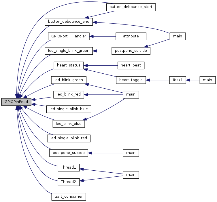
Referenced by button_debounce_end(), button_debounce_start(), GPIOPortF_Handler(), heart_status(), led_blink_blue(), led_blink_green(), led_blink_red(), led_single_blink_blue(), led_single_blink_green(), led_single_blink_red(), postpone_suicide(), Thread1(), Thread2(), and uart_consumer().
| void GPIOPinTypeADC | ( | uint32_t | ui32Port, |
| uint8_t | ui8Pins | ||
| ) |
Configures pin(s) for use as analog-to-digital converter inputs.
| ui32Port | is the base address of the GPIO port. |
| ui8Pins | is the bit-packed representation of the pin(s). |
The analog-to-digital converter input pins must be properly configured for the analog-to-digital peripheral to function correctly. This function provides the proper configuration for those pin(s).
The pin(s) are specified using a bit-packed byte, where each bit that is set identifies the pin to be accessed, and where bit 0 of the byte represents GPIO port pin 0, bit 1 represents GPIO port pin 1, and so on.
Definition at line 1081 of file gpio.c.
References ASSERT, GPIO_DIR_MODE_IN, GPIO_PIN_TYPE_ANALOG, GPIO_STRENGTH_2MA, GPIODirModeSet(), and GPIOPadConfigSet().
Referenced by adc_init().


| void GPIOPinTypeCAN | ( | uint32_t | ui32Port, |
| uint8_t | ui8Pins | ||
| ) |
Configures pin(s) for use as a CAN device.
| ui32Port | is the base address of the GPIO port. |
| ui8Pins | is the bit-packed representation of the pin(s). |
The CAN pins must be properly configured for the CAN peripherals to function correctly. This function provides a typical configuration for those pin(s); other configurations may work as well depending upon the board setup (for example, using the on-chip pull-ups).
The pin(s) are specified using a bit-packed byte, where each bit that is set identifies the pin to be accessed, and where bit 0 of the byte represents GPIO port pin 0, bit 1 represents GPIO port pin 1, and so on.
Definition at line 1133 of file gpio.c.
References ASSERT, GPIO_DIR_MODE_HW, GPIO_PIN_TYPE_STD, GPIO_STRENGTH_8MA, GPIODirModeSet(), and GPIOPadConfigSet().

| void GPIOPinTypeCIR | ( | uint32_t | ui32Port, |
| uint8_t | ui8Pins | ||
| ) |
Configures pin(s) for use as Consumer Infrared inputs or outputs.
| ui32Port | is the base address of the GPIO port. |
| ui8Pins | is the bit-packed representation of the pin(s). |
The GPIO pins must be properly configured in order to function correctly as Consumer Infrared pins. This function provides the proper configuration for those pin(s).
The pin(s) are specified using a bit-packed byte, where each bit that is set identifies the pin to be accessed, and where bit 0 of the byte represents GPIO port pin 0, bit 1 represents GPIO port pin 1, and so on.
Definition at line 2434 of file gpio.c.
References ASSERT, GPIO_DIR_MODE_HW, GPIO_PIN_TYPE_STD, GPIO_STRENGTH_2MA, GPIODirModeSet(), and GPIOPadConfigSet().

| void GPIOPinTypeComparator | ( | uint32_t | ui32Port, |
| uint8_t | ui8Pins | ||
| ) |
Configures pin(s) for use as an analog comparator input.
| ui32Port | is the base address of the GPIO port. |
| ui8Pins | is the bit-packed representation of the pin(s). |
The analog comparator input pins must be properly configured for the analog comparator to function correctly. This function provides the proper configuration for those pin(s).
The pin(s) are specified using a bit-packed byte, where each bit that is set identifies the pin to be accessed, and where bit 0 of the byte represents GPIO port pin 0, bit 1 represents GPIO port pin 1, and so on.
Definition at line 1183 of file gpio.c.
References ASSERT, GPIO_DIR_MODE_IN, GPIO_PIN_TYPE_ANALOG, GPIO_STRENGTH_2MA, GPIODirModeSet(), and GPIOPadConfigSet().

| void GPIOPinTypeEPI | ( | uint32_t | ui32Port, |
| uint8_t | ui8Pins | ||
| ) |
Configures pin(s) for use by the external peripheral interface.
| ui32Port | is the base address of the GPIO port. |
| ui8Pins | is the bit-packed representation of the pin(s). |
The external peripheral interface pins must be properly configured for the external peripheral interface to function correctly. This function provides a typical configuration for those pin(s); other configurations may work as well depending upon the board setup (for example, using the on-chip pull-ups).
The pin(s) are specified using a bit-packed byte, where each bit that is set identifies the pin to be accessed, and where bit 0 of the byte represents GPIO port pin 0, bit 1 represents GPIO port pin 1, and so on.
Definition at line 1237 of file gpio.c.
References ASSERT, GPIO_DIR_MODE_HW, GPIO_PIN_TYPE_STD, GPIO_STRENGTH_8MA, GPIODirModeSet(), and GPIOPadConfigSet().

| void GPIOPinTypeEthernetLED | ( | uint32_t | ui32Port, |
| uint8_t | ui8Pins | ||
| ) |
Configures pin(s) for use by the Ethernet peripheral as LED signals.
| ui32Port | is the base address of the GPIO port. |
| ui8Pins | is the bit-packed representation of the pin(s). |
The Ethernet peripheral provides four signals that can be used to drive an LED (for example, for link status/activity). This function provides a typical configuration for the pins.
The pin(s) are specified using a bit-packed byte, where each bit that is set identifies the pin to be accessed, and where bit 0 of the byte represents GPIO port pin 0, bit 1 represents GPIO port pin 1, and so on.
Definition at line 1287 of file gpio.c.
References ASSERT, GPIO_DIR_MODE_HW, GPIO_PIN_TYPE_STD, GPIO_STRENGTH_8MA, GPIODirModeSet(), and GPIOPadConfigSet().

| void GPIOPinTypeEthernetMII | ( | uint32_t | ui32Port, |
| uint8_t | ui8Pins | ||
| ) |
Configures pin(s) for use by the Ethernet peripheral as MII signals.
| ui32Port | is the base address of the GPIO port. |
| ui8Pins | is the bit-packed representation of the pin(s). |
The Ethernet peripheral on some parts provides a set of MII signals that are used to connect to an external PHY. This function provides a typical configuration for the pins.
The pin(s) are specified using a bit-packed byte, where each bit that is set identifies the pin to be accessed, and where bit 0 of the byte represents GPIO port pin 0, bit 1 represents GPIO port pin 1, and so on.
Definition at line 1337 of file gpio.c.
References ASSERT, GPIO_DIR_MODE_HW, GPIO_PIN_TYPE_STD, GPIO_STRENGTH_8MA, GPIODirModeSet(), and GPIOPadConfigSet().

| void GPIOPinTypeGPIOInput | ( | uint32_t | ui32Port, |
| uint8_t | ui8Pins | ||
| ) |
Configures pin(s) for use as GPIO inputs.
| ui32Port | is the base address of the GPIO port. |
| ui8Pins | is the bit-packed representation of the pin(s). |
The GPIO pins must be properly configured in order to function correctly as GPIO inputs. This function provides the proper configuration for those pin(s).
The pin(s) are specified using a bit-packed byte, where each bit that is set identifies the pin to be accessed, and where bit 0 of the byte represents GPIO port pin 0, bit 1 represents GPIO port pin 1, and so on.
Definition at line 1382 of file gpio.c.
References ASSERT, GPIO_DIR_MODE_IN, GPIO_PIN_TYPE_STD, GPIO_STRENGTH_2MA, GPIODirModeSet(), and GPIOPadConfigSet().

| void GPIOPinTypeGPIOOutput | ( | uint32_t | ui32Port, |
| uint8_t | ui8Pins | ||
| ) |
Configures pin(s) for use as GPIO outputs.
| ui32Port | is the base address of the GPIO port. |
| ui8Pins | is the bit-packed representation of the pin(s). |
The GPIO pins must be properly configured in order to function correctly as GPIO outputs. This function provides the proper configuration for those pin(s).
The pin(s) are specified using a bit-packed byte, where each bit that is set identifies the pin to be accessed, and where bit 0 of the byte represents GPIO port pin 0, bit 1 represents GPIO port pin 1, and so on.
Definition at line 1427 of file gpio.c.
References ASSERT, GPIO_DIR_MODE_OUT, GPIO_PIN_TYPE_STD, GPIO_STRENGTH_2MA, GPIODirModeSet(), and GPIOPadConfigSet().
Referenced by heart_init(), and main().

| void GPIOPinTypeGPIOOutputOD | ( | uint32_t | ui32Port, |
| uint8_t | ui8Pins | ||
| ) |
Configures pin(s) for use as GPIO open drain outputs.
| ui32Port | is the base address of the GPIO port. |
| ui8Pins | is the bit-packed representation of the pin(s). |
The GPIO pins must be properly configured in order to function correctly as GPIO outputs. This function provides the proper configuration for those pin(s).
The pin(s) are specified using a bit-packed byte, where each bit that is set identifies the pin to be accessed, and where bit 0 of the byte represents GPIO port pin 0, bit 1 represents GPIO port pin 1, and so on.
Definition at line 1472 of file gpio.c.
References ASSERT, GPIO_DIR_MODE_OUT, GPIO_PIN_TYPE_OD, GPIO_STRENGTH_2MA, GPIODirModeSet(), and GPIOPadConfigSet().

| void GPIOPinTypeI2C | ( | uint32_t | ui32Port, |
| uint8_t | ui8Pins | ||
| ) |
Configures pin for use as SDA by the I2C peripheral.
| ui32Port | is the base address of the GPIO port. |
| ui8Pins | is the bit-packed representation of the pin. |
The I2C pins must be properly configured for the I2C peripheral to function correctly. This function provides the proper configuration for the SDA pin.
The pin is specified using a bit-packed byte, where each bit that is set identifies the pin to be accessed, and where bit 0 of the byte represents GPIO port pin 0, bit 1 represents GPIO port pin 1, and so on.
Definition at line 1522 of file gpio.c.
References ASSERT, GPIO_DIR_MODE_HW, GPIO_PIN_TYPE_OD, GPIO_STRENGTH_2MA, GPIODirModeSet(), and GPIOPadConfigSet().

| void GPIOPinTypeI2CSCL | ( | uint32_t | ui32Port, |
| uint8_t | ui8Pins | ||
| ) |
Configures pin for use as SCL by the I2C peripheral.
| ui32Port | is the base address of the GPIO port. |
| ui8Pins | is the bit-packed representation of the pin. |
The I2C pins must be properly configured for the I2C peripheral to function correctly. This function provides the proper configuration for the SCL pin.
The pin is specified using a bit-packed byte, where each bit that is set identifies the pin to be accessed, and where bit 0 of the byte represents GPIO port pin 0, bit 1 represents GPIO port pin 1, and so on.
Definition at line 1572 of file gpio.c.
References ASSERT, GPIO_DIR_MODE_HW, GPIO_PIN_TYPE_STD, GPIO_STRENGTH_2MA, GPIODirModeSet(), and GPIOPadConfigSet().

| void GPIOPinTypeKBColumn | ( | uint32_t | ui32Port, |
| uint8_t | ui8Pins | ||
| ) |
Configures pin(s) for use as scan matrix keyboard columns (inputs).
| ui32Port | is the base address of the GPIO port. |
| ui8Pins | is the bit-packed representation of the pin(s). |
The GPIO pins must be properly configured in order to function correctly as scan matrix keyboard inputs. This function provides the proper configuration for those pin(s).
The pin(s) are specified using a bit-packed byte, where each bit that is set identifies the pin to be accessed, and where bit 0 of the byte represents GPIO port pin 0, bit 1 represents GPIO port pin 1, and so on.
Definition at line 2331 of file gpio.c.
References ASSERT, GPIO_DIR_MODE_HW, GPIO_PIN_TYPE_STD_WPU, GPIO_STRENGTH_2MA, GPIODirModeSet(), and GPIOPadConfigSet().

| void GPIOPinTypeKBRow | ( | uint32_t | ui32Port, |
| uint8_t | ui8Pins | ||
| ) |
Configures pin(s) for use as scan matrix keyboard rows (outputs).
| ui32Port | is the base address of the GPIO port. |
| ui8Pins | is the bit-packed representation of the pin(s). |
The GPIO pins must be properly configured in order to function correctly as scan matrix keyboard outputs. This function provides the proper configuration for those pin(s).
The pin(s) are specified using a bit-packed byte, where each bit that is set identifies the pin to be accessed, and where bit 0 of the byte represents GPIO port pin 0, bit 1 represents GPIO port pin 1, and so on.
Definition at line 2280 of file gpio.c.
References ASSERT, GPIO_DIR_MODE_HW, GPIO_PIN_TYPE_STD, GPIO_STRENGTH_2MA, GPIODirModeSet(), and GPIOPadConfigSet().

| void GPIOPinTypeLCD | ( | uint32_t | ui32Port, |
| uint8_t | ui8Pins | ||
| ) |
Configures pin(s) for use by the LCD Controller.
| ui32Port | is the base address of the GPIO port. |
| ui8Pins | is the bit-packed representation of the pin(s). |
The LCD controller pins must be properly configured for the LCD controller to function correctly. This function provides a typical configuration for those pin(s); other configurations may work as well depending upon the board setup (for example, using the on-chip pull-ups).
The pin(s) are specified using a bit-packed byte, where each bit that is set identifies the pin to be accessed, and where bit 0 of the byte represents GPIO port pin 0, bit 1 represents GPIO port pin 1, and so on.
Definition at line 1623 of file gpio.c.
References ASSERT, GPIO_DIR_MODE_HW, GPIO_PIN_TYPE_STD, GPIO_STRENGTH_8MA, GPIODirModeSet(), and GPIOPadConfigSet().

| void GPIOPinTypeLEDSeq | ( | uint32_t | ui32Port, |
| uint8_t | ui8Pins | ||
| ) |
Configures pin(s) for use as an LED sequencer output.
| ui32Port | is the base address of the GPIO port. |
| ui8Pins | is the bit-packed representation of the pin(s). |
The GPIO pins must be properly configured in order to function correctly as LED sequencers. This function provides the proper configuration for those pin(s).
The pin(s) are specified using a bit-packed byte, where each bit that is set identifies the pin to be accessed, and where bit 0 of the byte represents GPIO port pin 0, bit 1 represents GPIO port pin 1, and so on.
Definition at line 2382 of file gpio.c.
References ASSERT, GPIO_DIR_MODE_HW, GPIO_PIN_TYPE_STD, GPIO_STRENGTH_8MA, GPIODirModeSet(), and GPIOPadConfigSet().

| void GPIOPinTypeLPC | ( | uint32_t | ui32Port, |
| uint8_t | ui8Pins | ||
| ) |
Configures pin(s) for use by the LPC module.
| ui32Port | is the base address of the GPIO port. |
| ui8Pins | is the bit-packed representation of the pin(s). |
The LPC pins must be properly configured for the LPC module to function correctly. This function provides a typical configuration for those pin(s); other configurations may work as well depending upon the board setup (for example, using the on-chip pull-ups).
The pin(s) are specified using a bit-packed byte, where each bit that is set identifies the pin to be accessed, and where bit 0 of the byte represents GPIO port pin 0, bit 1 represents GPIO port pin 1, and so on.
Definition at line 1674 of file gpio.c.
References ASSERT, GPIO_DIR_MODE_HW, GPIO_PIN_TYPE_STD, GPIO_STRENGTH_8MA, GPIODirModeSet(), and GPIOPadConfigSet().

| void GPIOPinTypePECIRx | ( | uint32_t | ui32Port, |
| uint8_t | ui8Pins | ||
| ) |
Configures a pin for receive use by the PECI module.
| ui32Port | is the base address of the GPIO port. |
| ui8Pins | is the bit-packed representation of the pin(s). |
The PECI receive pin must be properly configured for the PECI module to function correctly. This function provides a typical configuration for that pin.
The pin is specified using a bit-packed byte, where each bit that is set identifies the pin to be accessed, and where bit 0 of the byte represents GPIO port pin 0, bit 1 represents GPIO port pin 1, and so on.
Definition at line 1724 of file gpio.c.
References ASSERT, GPIO_DIR_MODE_IN, GPIO_PIN_TYPE_ANALOG, GPIO_STRENGTH_2MA, GPIODirModeSet(), and GPIOPadConfigSet().

| void GPIOPinTypePECITx | ( | uint32_t | ui32Port, |
| uint8_t | ui8Pins | ||
| ) |
Configures a pin for transmit use by the PECI module.
| ui32Port | is the base address of the GPIO port. |
| ui8Pins | is the bit-packed representation of the pin(s). |
The PECI transmit pin must be properly configured for the PECI module to function correctly. This function provides a typical configuration for that pin.
The pin is specified using a bit-packed byte, where each bit that is set identifies the pin to be accessed, and where bit 0 of the byte represents GPIO port pin 0, bit 1 represents GPIO port pin 1, and so on.
Definition at line 1775 of file gpio.c.
References ASSERT, GPIO_DIR_MODE_HW, GPIO_PIN_TYPE_STD, GPIO_STRENGTH_2MA, GPIODirModeSet(), and GPIOPadConfigSet().

| void GPIOPinTypePWM | ( | uint32_t | ui32Port, |
| uint8_t | ui8Pins | ||
| ) |
Configures pin(s) for use by the PWM peripheral.
| ui32Port | is the base address of the GPIO port. |
| ui8Pins | is the bit-packed representation of the pin(s). |
The PWM pins must be properly configured for the PWM peripheral to function correctly. This function provides a typical configuration for those pin(s); other configurations may work as well depending upon the board setup (for example, using the on-chip pull-ups).
The pin(s) are specified using a bit-packed byte, where each bit that is set identifies the pin to be accessed, and where bit 0 of the byte represents GPIO port pin 0, bit 1 represents GPIO port pin 1, and so on.
Definition at line 1826 of file gpio.c.
References ASSERT, GPIO_DIR_MODE_HW, GPIO_PIN_TYPE_STD, GPIO_STRENGTH_2MA, GPIODirModeSet(), and GPIOPadConfigSet().

| void GPIOPinTypeQEI | ( | uint32_t | ui32Port, |
| uint8_t | ui8Pins | ||
| ) |
Configures pin(s) for use by the QEI peripheral.
| ui32Port | is the base address of the GPIO port. |
| ui8Pins | is the bit-packed representation of the pin(s). |
The QEI pins must be properly configured for the QEI peripheral to function correctly. This function provides a typical configuration for those pin(s); other configurations may work as well depending upon the board setup (for example, not using the on-chip pull-ups).
The pin(s) are specified using a bit-packed byte, where each bit that is set identifies the pin to be accessed, and where bit 0 of the byte represents GPIO port pin 0, bit 1 represents GPIO port pin 1, and so on.
Definition at line 1877 of file gpio.c.
References ASSERT, GPIO_DIR_MODE_HW, GPIO_PIN_TYPE_STD_WPU, GPIO_STRENGTH_2MA, GPIODirModeSet(), and GPIOPadConfigSet().

| void GPIOPinTypeSSI | ( | uint32_t | ui32Port, |
| uint8_t | ui8Pins | ||
| ) |
Configures pin(s) for use by the SSI peripheral.
| ui32Port | is the base address of the GPIO port. |
| ui8Pins | is the bit-packed representation of the pin(s). |
The SSI pins must be properly configured for the SSI peripheral to function correctly. This function provides a typical configuration for those pin(s); other configurations may work as well depending upon the board setup (for example, using the on-chip pull-ups).
The pin(s) are specified using a bit-packed byte, where each bit that is set identifies the pin to be accessed, and where bit 0 of the byte represents GPIO port pin 0, bit 1 represents GPIO port pin 1, and so on.
Definition at line 1929 of file gpio.c.
References ASSERT, GPIO_DIR_MODE_HW, GPIO_PIN_TYPE_STD, GPIO_STRENGTH_2MA, GPIODirModeSet(), and GPIOPadConfigSet().

| void GPIOPinTypeTimer | ( | uint32_t | ui32Port, |
| uint8_t | ui8Pins | ||
| ) |
Configures pin(s) for use by the Timer peripheral.
| ui32Port | is the base address of the GPIO port. |
| ui8Pins | is the bit-packed representation of the pin(s). |
The CCP pins must be properly configured for the timer peripheral to function correctly. This function provides a typical configuration for those pin(s); other configurations may work as well depending upon the board setup (for example, using the on-chip pull-ups).
The pin(s) are specified using a bit-packed byte, where each bit that is set identifies the pin to be accessed, and where bit 0 of the byte represents GPIO port pin 0, bit 1 represents GPIO port pin 1, and so on.
Definition at line 1980 of file gpio.c.
References ASSERT, GPIO_DIR_MODE_HW, GPIO_PIN_TYPE_STD, GPIO_STRENGTH_2MA, GPIODirModeSet(), and GPIOPadConfigSet().

| void GPIOPinTypeUART | ( | uint32_t | ui32Port, |
| uint8_t | ui8Pins | ||
| ) |
Configures pin(s) for use by the UART peripheral.
| ui32Port | is the base address of the GPIO port. |
| ui8Pins | is the bit-packed representation of the pin(s). |
The UART pins must be properly configured for the UART peripheral to function correctly. This function provides a typical configuration for those pin(s); other configurations may work as well depending upon the board setup (for example, using the on-chip pull-ups).
The pin(s) are specified using a bit-packed byte, where each bit that is set identifies the pin to be accessed, and where bit 0 of the byte represents GPIO port pin 0, bit 1 represents GPIO port pin 1, and so on.
Definition at line 2031 of file gpio.c.
References ASSERT, GPIO_DIR_MODE_HW, GPIO_PIN_TYPE_STD, GPIO_STRENGTH_2MA, GPIODirModeSet(), and GPIOPadConfigSet().
Referenced by main(), and uart_init().

| void GPIOPinTypeUSBAnalog | ( | uint32_t | ui32Port, |
| uint8_t | ui8Pins | ||
| ) |
Configures pin(s) for use by the USB peripheral.
| ui32Port | is the base address of the GPIO port. |
| ui8Pins | is the bit-packed representation of the pin(s). |
USB analog pins must be properly configured for the USB peripheral to function correctly. This function provides the proper configuration for any USB analog pin(s).
The pin(s) are specified using a bit-packed byte, where each bit that is set identifies the pin to be accessed, and where bit 0 of the byte represents GPIO port pin 0, bit 1 represents GPIO port pin 1, and so on.
Definition at line 2081 of file gpio.c.
References ASSERT, GPIO_DIR_MODE_IN, GPIO_PIN_TYPE_ANALOG, GPIO_STRENGTH_2MA, GPIODirModeSet(), and GPIOPadConfigSet().

| void GPIOPinTypeUSBDigital | ( | uint32_t | ui32Port, |
| uint8_t | ui8Pins | ||
| ) |
Configures pin(s) for use by the USB peripheral.
| ui32Port | is the base address of the GPIO port. |
| ui8Pins | is the bit-packed representation of the pin(s). |
USB digital pins must be properly configured for the USB peripheral to function correctly. This function provides a typical configuration for the digital USB pin(s); other configurations may work as well depending upon the board setup (for example, using the on-chip pull-ups).
This function should only be used with EPEN and PFAULT pins as all other USB pins are analog in nature or are not used in devices without OTG functionality.
The pin(s) are specified using a bit-packed byte, where each bit that is set identifies the pin to be accessed, and where bit 0 of the byte represents GPIO port pin 0, bit 1 represents GPIO port pin 1, and so on.
Definition at line 2137 of file gpio.c.
References ASSERT, GPIO_DIR_MODE_HW, GPIO_PIN_TYPE_STD, GPIO_STRENGTH_2MA, GPIODirModeSet(), and GPIOPadConfigSet().

| void GPIOPinTypeWakeHigh | ( | uint32_t | ui32Port, |
| uint8_t | ui8Pins | ||
| ) |
Configures pin(s) for use as a hibernate wake-on-high source.
| ui32Port | is the base address of the GPIO port. |
| ui8Pins | is the bit-packed representation of the pin(s). |
The GPIO pins must be properly configured in order to function correctly as hibernate wake-high inputs. This function provides the proper configuration for those pin(s).
The pin(s) are specified using a bit-packed byte, where each bit that is set identifies the pin to be accessed, and where bit 0 of the byte represents GPIO port pin 0, bit 1 represents GPIO port pin 1, and so on.
Definition at line 2182 of file gpio.c.
References ASSERT, GPIO_DIR_MODE_IN, GPIO_PIN_TYPE_WAKE_HIGH, GPIO_STRENGTH_2MA, GPIODirModeSet(), and GPIOPadConfigSet().

| void GPIOPinTypeWakeLow | ( | uint32_t | ui32Port, |
| uint8_t | ui8Pins | ||
| ) |
Configures pin(s) for use as a hibernate wake-on-low source.
| ui32Port | is the base address of the GPIO port. |
| ui8Pins | is the bit-packed representation of the pin(s). |
The GPIO pins must be properly configured in order to function correctly as hibernate wake-low inputs. This function provides the proper configuration for those pin(s).
The pin(s) are specified using a bit-packed byte, where each bit that is set identifies the pin to be accessed, and where bit 0 of the byte represents GPIO port pin 0, bit 1 represents GPIO port pin 1, and so on.
Definition at line 2228 of file gpio.c.
References ASSERT, GPIO_DIR_MODE_IN, GPIO_PIN_TYPE_WAKE_LOW, GPIO_STRENGTH_2MA, GPIODirModeSet(), and GPIOPadConfigSet().

| uint32_t GPIOPinWakeStatus | ( | uint32_t | ui32Port | ) |
Retrieves the wake pins status.
| ui32Port | is the base address of the GPIO port. |
This function returns the GPIO wake pin status values. The returned bitfield shows low or high pin state via a value of 0 or 1.
Definition at line 2476 of file gpio.c.
References GPIO_O_WAKESTAT.
| void GPIOPinWrite | ( | uint32_t | ui32Port, |
| uint8_t | ui8Pins, | ||
| uint8_t | ui8Val | ||
| ) |
Writes a value to the specified pin(s).
| ui32Port | is the base address of the GPIO port. |
| ui8Pins | is the bit-packed representation of the pin(s). |
| ui8Val | is the value to write to the pin(s). |
Writes the corresponding bit values to the output pin(s) specified by ui8Pins. Writing to a pin configured as an input pin has no effect.
The pin(s) are specified using a bit-packed byte, where each bit that is set identifies the pin to be accessed, and where bit 0 of the byte represents GPIO port pin 0, bit 1 represents GPIO port pin 1, and so on.
Definition at line 1038 of file gpio.c.
References ASSERT, GPIO_O_DATA, and HWREG.
Referenced by heart_beat(), heart_off(), heart_on(), heart_toggle(), led_blink_blue(), led_blink_green(), led_blink_red(), led_single_blink_blue(), led_single_blink_green(), led_single_blink_red(), postpone_suicide(), Thread1(), Thread2(), and uart_consumer().
|
static |
|
static |
|
static |
|
static |
Definition at line 90 of file gpio.c.
Referenced by _GPIOIntNumberGet().
|
static |
Definition at line 120 of file gpio.c.
Referenced by _GPIOIntNumberGet().
 1.8.9.1
