EE445M RTOS
Taken at the University of Texas Spring 2015
Epi_api

Macros

#define EPI_HB8_CS_MASK
 
#define EPI_HB16_CS_MASK   (EPI_HB8_CS_MASK | EPI_HB16_BURST_TRAFFIC)
 

Functions

void EPIWorkaroundWordWrite (uint32_t *pui32Addr, uint32_t ui32Value)
 
uint32_t EPIWorkaroundWordRead (uint32_t *pui32Addr)
 
void EPIWorkaroundHWordWrite (uint16_t *pui16Addr, uint16_t ui16Value)
 
uint16_t EPIWorkaroundHWordRead (uint16_t *pui16Addr)
 
void EPIWorkaroundByteWrite (uint8_t *pui8Addr, uint8_t ui8Value)
 
uint8_t EPIWorkaroundByteRead (uint8_t *pui8Addr)
 
void EPIModeSet (uint32_t ui32Base, uint32_t ui32Mode)
 
void EPIDividerSet (uint32_t ui32Base, uint32_t ui32Divider)
 
void EPIDividerCSSet (uint32_t ui32Base, uint32_t ui32CS, uint32_t ui32Divider)
 
void EPIDMATxCount (uint32_t ui32Base, uint32_t ui32Count)
 
void EPIConfigSDRAMSet (uint32_t ui32Base, uint32_t ui32Config, uint32_t ui32Refresh)
 
void EPIConfigHB8Set (uint32_t ui32Base, uint32_t ui32Config, uint32_t ui32MaxWait)
 
void EPIConfigHB16Set (uint32_t ui32Base, uint32_t ui32Config, uint32_t ui32MaxWait)
 
void EPIConfigHB8CSSet (uint32_t ui32Base, uint32_t ui32CS, uint32_t ui32Config)
 
void EPIConfigHB16CSSet (uint32_t ui32Base, uint32_t ui32CS, uint32_t ui32Config)
 
void EPIConfigHB8TimingSet (uint32_t ui32Base, uint32_t ui32CS, uint32_t ui32Config)
 
void EPIConfigHB16TimingSet (uint32_t ui32Base, uint32_t ui32CS, uint32_t ui32Config)
 
void EPIPSRAMConfigRegSet (uint32_t ui32Base, uint32_t ui32CS, uint32_t ui32CR)
 
void EPIPSRAMConfigRegRead (uint32_t ui32Base, uint32_t ui32CS)
 
bool EPIPSRAMConfigRegGetNonBlocking (uint32_t ui32Base, uint32_t ui32CS, uint32_t *pui32CR)
 
uint32_t EPIPSRAMConfigRegGet (uint32_t ui32Base, uint32_t ui32CS)
 
void EPIConfigGPModeSet (uint32_t ui32Base, uint32_t ui32Config, uint32_t ui32FrameCount, uint32_t ui32MaxWait)
 
void EPIAddressMapSet (uint32_t ui32Base, uint32_t ui32Map)
 
void EPINonBlockingReadConfigure (uint32_t ui32Base, uint32_t ui32Channel, uint32_t ui32DataSize, uint32_t ui32Address)
 
void EPINonBlockingReadStart (uint32_t ui32Base, uint32_t ui32Channel, uint32_t ui32Count)
 
void EPINonBlockingReadStop (uint32_t ui32Base, uint32_t ui32Channel)
 
uint32_t EPINonBlockingReadCount (uint32_t ui32Base, uint32_t ui32Channel)
 
uint32_t EPINonBlockingReadAvail (uint32_t ui32Base)
 
uint32_t EPINonBlockingReadGet32 (uint32_t ui32Base, uint32_t ui32Count, uint32_t *pui32Buf)
 
uint32_t EPINonBlockingReadGet16 (uint32_t ui32Base, uint32_t ui32Count, uint16_t *pui16Buf)
 
uint32_t EPINonBlockingReadGet8 (uint32_t ui32Base, uint32_t ui32Count, uint8_t *pui8Buf)
 
void EPIFIFOConfig (uint32_t ui32Base, uint32_t ui32Config)
 
uint32_t EPIWriteFIFOCountGet (uint32_t ui32Base)
 
void EPIIntEnable (uint32_t ui32Base, uint32_t ui32IntFlags)
 
void EPIIntDisable (uint32_t ui32Base, uint32_t ui32IntFlags)
 
uint32_t EPIIntStatus (uint32_t ui32Base, bool bMasked)
 
uint32_t EPIIntErrorStatus (uint32_t ui32Base)
 
void EPIIntErrorClear (uint32_t ui32Base, uint32_t ui32ErrFlags)
 
static uint32_t _EPIIntNumberGet (uint32_t ui32Base)
 
void EPIIntRegister (uint32_t ui32Base, void(*pfnHandler)(void))
 
void EPIIntUnregister (uint32_t ui32Base)
 

Detailed Description

Macro Definition Documentation

#define EPI_HB16_CS_MASK   (EPI_HB8_CS_MASK | EPI_HB16_BURST_TRAFFIC)

Definition at line 67 of file epi.c.

Referenced by EPIConfigHB16CSSet().

#define EPI_HB8_CS_MASK
Value:
#define EPI_HB8_RDHIGH
Definition: epi.h:111
#define EPI_HB8_WRHIGH
Definition: epi.h:110
#define EPI_HB8_WRWAIT_3
Definition: epi.h:117
#define EPI_HB8_MODE_FIFO
Definition: epi.h:125
#define EPI_HB8_ALE_HIGH
Definition: epi.h:112
#define EPI_HB8_RDWAIT_3
Definition: epi.h:121

Definition at line 63 of file epi.c.

Referenced by EPIConfigHB8CSSet().

Function Documentation

static uint32_t _EPIIntNumberGet ( uint32_t  ui32Base)
static

Returns the interrupt number for a given EPI base address.

Parameters
ui32Baseis the base address of the EPI module.

This function returns the interrupt number for the EPI module with the base address passed in the ui32Base parameter.

Returns
Returns the EPI interrupt number or 0 if the interrupt does not exist.

Definition at line 2070 of file epi.c.

References ASSERT, CLASS_IS_TM4C129, EPI0_BASE, and INT_EPI0_TM4C129.

Referenced by EPIIntRegister(), and EPIIntUnregister().

2071 {
2072  uint32_t ui32Int;
2073 
2074  //
2075  // Check the arguments.
2076  //
2077  ASSERT(ui32Base == EPI0_BASE);
2078 
2079  //
2080  // By default, assume EPI is not supported.
2081  //
2082  ui32Int = 0;
2083 
2084  if(CLASS_IS_TM4C129)
2085  {
2086  ui32Int = INT_EPI0_TM4C129;
2087  }
2088 
2089  return(ui32Int);
2090 }
#define ASSERT(expr)
Definition: debug.h:67
#define EPI0_BASE
Definition: hw_memmap.h:129
#define INT_EPI0_TM4C129
Definition: hw_ints.h:226
#define CLASS_IS_TM4C129
Definition: hw_types.h:99

Here is the caller graph for this function:

void EPIAddressMapSet ( uint32_t  ui32Base,
uint32_t  ui32Map 
)

Configures the address map for the external interface.

Parameters
ui32Baseis the EPI module base address.
ui32Mapis the address mapping configuration.

This function is used to configure the address mapping for the external interface, which then determines the base address of the external memory or device within the processor peripheral and/or memory space.

The parameter ui32Map is the logical OR of the following:

  • Peripheral address space size, select one of:
    • EPI_ADDR_PER_SIZE_256B sets the peripheral address space to 256 bytes.
    • EPI_ADDR_PER_SIZE_64KB sets the peripheral address space to 64 Kbytes.
    • EPI_ADDR_PER_SIZE_16MB sets the peripheral address space to 16 Mbytes.
    • EPI_ADDR_PER_SIZE_256MB sets the peripheral address space to 256 Mbytes.
  • Peripheral base address, select one of:
    • EPI_ADDR_PER_BASE_NONE sets the peripheral base address to none.
    • EPI_ADDR_PER_BASE_A sets the peripheral base address to 0xA0000000.
    • EPI_ADDR_PER_BASE_C sets the peripheral base address to 0xC0000000.
  • RAM address space, select one of:
    • EPI_ADDR_RAM_SIZE_256B sets the RAM address space to 256 bytes.
    • EPI_ADDR_RAM_SIZE_64KB sets the RAM address space to 64 Kbytes.
    • EPI_ADDR_RAM_SIZE_16MB sets the RAM address space to 16 Mbytes.
    • EPI_ADDR_RAM_SIZE_256MB sets the RAM address space to 256 Mbytes.
  • RAM base address, select one of:
    • EPI_ADDR_RAM_BASE_NONE sets the RAM space address to none.
    • EPI_ADDR_RAM_BASE_6 sets the RAM space address to 0x60000000.
    • EPI_ADDR_RAM_BASE_8 sets the RAM space address to 0x80000000.
  • EPI_ADDR_RAM_QUAD_MODE maps CS0n to 0x60000000, CS1n to 0x80000000, CS2n to 0xA0000000, and CS3n to 0xC0000000.
  • EPI_ADDR_CODE_SIZE_256B sets an external code size of 256 bytes, range 0x00 to 0xFF.
  • EPI_ADDR_CODE_SIZE_64KB sets an external code size of 64 Kbytes, range 0x0000 to 0xFFFF.
  • EPI_ADDR_CODE_SIZE_16MB sets an external code size of 16 Mbytes, range 0x000000 to 0xFFFFFF.
  • EPI_ADDR_CODE_SIZE_256MB sets an external code size of 256 Mbytes, range 0x0000000 to 0xFFFFFFF.
  • EPI_ADDR_CODE_BASE_NONE sets external code base to not mapped.
  • EPI_ADDR_CODE_BASE_1 sets external code base to 0x10000000.
Note
The availability of EPI_ADDR_RAM_QUAD_MODE and EPI_ADDR_CODE_* varies based on the Tiva part in use. Please consult the data sheet to determine if these features are available.
Returns
None.

Definition at line 1415 of file epi.c.

References ASSERT, EPI0_BASE, EPI_O_ADDRMAP, and HWREG.

1416 {
1417  //
1418  // Check the arguments.
1419  //
1420  ASSERT(ui32Base == EPI0_BASE);
1421  ASSERT(ui32Map < 0x1000);
1422 
1423  //
1424  // Set the value of the address mapping register.
1425  //
1426  HWREG(ui32Base + EPI_O_ADDRMAP) = ui32Map;
1427 }
#define HWREG(x)
Definition: hw_types.h:48
#define ASSERT(expr)
Definition: debug.h:67
#define EPI0_BASE
Definition: hw_memmap.h:129
#define EPI_O_ADDRMAP
Definition: hw_epi.h:59
void EPIConfigGPModeSet ( uint32_t  ui32Base,
uint32_t  ui32Config,
uint32_t  ui32FrameCount,
uint32_t  ui32MaxWait 
)

Configures the interface for general-purpose mode operation.

Parameters
ui32Baseis the EPI module base address.
ui32Configis the interface configuration.
ui32FrameCountis the frame size in clocks, if the frame signal is used (0-15).
ui32MaxWaitis currently not used.

This function is used to configure the interface when used in general-purpose operation as chosen with the function EPIModeSet(). The parameter ui32Config is the logical OR of the following:

  • EPI_GPMODE_CLKPIN interface clock as output on a pin.
  • EPI_GPMODE_CLKGATE clock is stopped when there is no transaction, otherwise it is free-running.
  • EPI_GPMODE_FRAME50 framing signal is 50/50 duty cycle, otherwise it is a pulse.
  • EPI_GPMODE_WRITE2CYCLE a two-cycle write is used, otherwise a single-cycle write is used.
  • Address bus size, select one of:
    • EPI_GPMODE_ASIZE_NONE sets no address bus.
    • EPI_GPMODE_ASIZE_4 sets an address bus size of 4 bits.
    • EPI_GPMODE_ASIZE_12 sets an address bus size of 12 bits.
    • EPI_GPMODE_ASIZE_20 sets an address bus size of 20 bits.
  • Data bus size, select one of:
    • EPI_GPMODE_DSIZE_8 sets a data bus size of 8 bits.
    • EPI_GPMODE_DSIZE_16 sets a data bus size of 16 bits.
    • EPI_GPMODE_DSIZE_24 sets a data bus size of 24 bits.
    • EPI_GPMODE_DSIZE_32 sets a data bus size of 32 bits.

The parameter ui32FrameCount is the number of clocks used to form the framing signal, if the framing signal is used. The behavior depends on whether the frame signal is a pulse or a 50/50 duty cycle.

Returns
None.

Definition at line 1335 of file epi.c.

References ASSERT, EPI0_BASE, EPI_GPCFG_FRMCNT_M, EPI_GPCFG_FRMCNT_S, EPI_O_GPCFG, and HWREG.

1337 {
1338  //
1339  // Check the arguments.
1340  //
1341  ASSERT(ui32Base == EPI0_BASE);
1342  ASSERT(ui32FrameCount < 16);
1343  ASSERT(ui32MaxWait < 256);
1344 
1345  //
1346  // Fill in the frame count field of the configuration word.
1347  //
1348  ui32Config &= ~EPI_GPCFG_FRMCNT_M;
1349  ui32Config |= ui32FrameCount << EPI_GPCFG_FRMCNT_S;
1350 
1351  //
1352  // Write the non-moded configuration register.
1353  //
1354  HWREG(ui32Base + EPI_O_GPCFG) = ui32Config;
1355 }
#define HWREG(x)
Definition: hw_types.h:48
#define EPI_O_GPCFG
Definition: hw_epi.h:53
#define EPI_GPCFG_FRMCNT_S
Definition: hw_epi.h:193
#define ASSERT(expr)
Definition: debug.h:67
#define EPI0_BASE
Definition: hw_memmap.h:129
#define EPI_GPCFG_FRMCNT_M
Definition: hw_epi.h:178
void EPIConfigHB16CSSet ( uint32_t  ui32Base,
uint32_t  ui32CS,
uint32_t  ui32Config 
)

Sets the individual chip select configuration for the Host-bus 16 interface.

Parameters
ui32Baseis the EPI module base address.
ui32CSis the chip select value to configure.
ui32Configis the configuration settings.

This function is used to configure individual chip select settings for the Host-bus 16 interface mode. EPIConfigHB16Set() must have been set up with the EPI_HB16_CSBAUD flag for the individual chip select configuration option to be available.

The ui32Base parameter is the base address for the EPI hardware module. The ui32CS parameter specifies the chip select to configure and has a valid range of 0-3. The parameter ui32Config is the logical OR the following:

  • Host-bus 16 submode, select one of:
    • EPI_HB16_MODE_ADMUX sets data and address muxed, AD[15:0].
    • EPI_HB16_MODE_ADDEMUX sets up data and address separate, D[15:0].
    • EPI_HB16_MODE_SRAM same as EPI_HB8_MODE_ADDEMUX, but uses address switch for multiple reads instead of OEn strobing, D[15:0].
    • EPI_HB16_MODE_FIFO adds XFIFO with sense of XFIFO full and XFIFO empty, D[15:0]. This feature is only available on CS0n and CS1n.
  • EPI_HB16_WRHIGH sets active high write strobe, otherwise it is active low.
  • EPI_HB16_RDHIGH sets active high read strobe, otherwise it is active low.
  • Write wait state when EPI_HB16_BAUD is used, select one of:
    • EPI_HB16_WRWAIT_0 sets write wait state to 2 EPI clocks (default).
    • EPI_HB16_WRWAIT_1 sets write wait state to 4 EPI clocks.
    • EPI_HB16_WRWAIT_2 sets write wait state to 6 EPI clocks.
    • EPI_HB16_WRWAIT_3 sets write wait state to 8 EPI clocks.
  • Read wait state when EPI_HB16_BAUD is used, select one of:
    • EPI_HB16_RDWAIT_0 sets read wait state to 2 EPI clocks (default).
    • EPI_HB16_RDWAIT_1 sets read wait state to 4 EPI clocks.
    • EPI_HB16_RDWAIT_2 sets read wait state to 6 EPI clocks.
    • EPI_HB16_RDWAIT_3 sets read wait state to 8 EPI clocks.
  • EPI_HB16_ALE_HIGH sets the address latch active high (default).
  • EPI_HB16_ALE_LOW sets address latch active low.
  • EPI_HB16_BURST_TRAFFIC enables burst traffic. Only valid with EPI_HB16_MODE_ADMUX and a chip select configuration that utilizes an ALE.
Note
The availability of the unique chip select configuration within the Host-bus 16 interface mode varies based on the Tiva part in use. Please consult the data sheet to determine if this feature is available.
Returns
None.

Definition at line 877 of file epi.c.

References ASSERT, EPI0_BASE, EPI_HB16_CS_MASK, EPI_O_HB16CFG, EPI_O_HB16CFG3, and HWREG.

878 {
879  uint32_t ui32Offset, ui32Reg;
880 
881  //
882  // Check the arguments.
883  //
884  ASSERT(ui32Base == EPI0_BASE);
885  ASSERT(ui32CS < 4);
886 
887  //
888  // Determine the register offset based on the ui32CS provided.
889  //
890  if(ui32CS < 2)
891  {
892  ui32Offset = EPI_O_HB16CFG + (ui32CS << 2);
893  }
894  else
895  {
896  ui32Offset = EPI_O_HB16CFG3 + ((ui32CS - 2) << 2);
897  }
898 
899  //
900  // Preserve the bits that will not be modified.
901  //
902  ui32Reg = HWREG(ui32Base + ui32Offset) & ~EPI_HB16_CS_MASK;
903 
904  //
905  // Write the target chip select HostBus16 configuration fields.
906  //
907  HWREG(ui32Base + ui32Offset) = (ui32Reg | ui32Config);
908 }
#define HWREG(x)
Definition: hw_types.h:48
#define ASSERT(expr)
Definition: debug.h:67
#define EPI_O_HB16CFG3
Definition: hw_epi.h:85
#define EPI_O_HB16CFG
Definition: hw_epi.h:52
#define EPI0_BASE
Definition: hw_memmap.h:129
#define EPI_HB16_CS_MASK
Definition: epi.c:67
void EPIConfigHB16Set ( uint32_t  ui32Base,
uint32_t  ui32Config,
uint32_t  ui32MaxWait 
)

Configures the interface for Host-bus 16 operation.

Parameters
ui32Baseis the EPI module base address.
ui32Configis the interface configuration.
ui32MaxWaitis the maximum number of external clocks to wait if a FIFO ready signal is holding off the transaction.

This function is used to configure the interface when used in Host-bus 16 operation as chosen with the function EPIModeSet(). The parameter ui32Config is the logical OR of the following:

  • Host-bus 16 submode, select one of:
    • EPI_HB16_MODE_ADMUX sets data and address muxed, AD[15:0].
    • EPI_HB16_MODE_ADDEMUX sets up data and address as separate, D[15:0].
    • EPI_HB16_MODE_SRAM sets as EPI_HB16_MODE_ADDEMUX but uses address switch for multiple reads instead of OEn strobing, D[15:0].
    • EPI_HB16_MODE_FIFO addes XFIFO controls with sense of XFIFO full and XFIFO empty, D[15:0]. This submode uses no address or ALE.
  • EPI_HB16_USE_TXEMPTY enables TXEMPTY signal with FIFO.
  • EPI_HB16_USE_RXFULL enables RXFULL signal with FIFO.
  • EPI_HB16_WRHIGH use active high write strobe, otherwise it is active low.
  • EPI_HB16_RDHIGH use active high read strobe, otherwise it is active low.
  • Write wait state, select one of:
    • EPI_HB16_WRWAIT_0 sets write wait state to 2 EPI clocks.
    • EPI_HB16_WRWAIT_1 sets write wait state to 4 EPI clocks.
    • EPI_HB16_WRWAIT_2 sets write wait state to 6 EPI clocks.
    • EPI_HB16_WRWAIT_3 sets write wait state to 8 EPI clocks.
  • Read wait state, select one of:
    • EPI_HB16_RDWAIT_0 sets read wait state to 2 EPI clocks.
    • EPI_HB16_RDWAIT_1 sets read wait state to 4 EPI clocks.
    • EPI_HB16_RDWAIT_2 sets read wait state to 6 EPI clocks.
    • EPI_HB16_RDWAIT_3 sets read wait state to 8 EPI clocks.
  • EPI_HB16_WORD_ACCESS use Word Access mode to route bytes to the correct byte lanes allowing data to be stored in bits [31:16]. If absent, all data transfers use bits [15:0].
Note
EPI_HB16_WORD_ACCESS is not available on all parts. Please consult the data sheet to determine if this feature is available.
  • EPI_HB16_CLOCK_GATE_IDLE holds the EPI clock low when no data is available to read or write.
  • EPI_HB16_CLOCK_INVERT inverts the EPI clock.
  • EPI_HB16_IN_READY_EN sets EPIS032 as a ready/stall signal, active high.
  • EPI_HB16_IN_READY_EN_INVERTED sets EPIS032 as ready/stall signal, active low.
  • Address latch logic, select one of:
    • EPI_HB16_ALE_HIGH sets the address latch active high (default).
    • EPI_HB16_ALE_LOW sets address latch active low.
  • EPI_HB16_BURST_TRAFFIC enables burst traffic. Only valid with EPI_HB16_MODE_ADMUX and a chip select configuration that utilizes an ALE.
  • EPI_HB16_BSEL enables byte selects. In this mode, two EPI signals operate as byte selects allowing 8-bit transfers. If this flag is not specified, data must be read and written using only 16-bit transfers.
  • EPI_HB16_CSBAUD use different baud rates when accessing devices on each chip select. CS0n uses the baud rate specified by the lower 16 bits of the divider passed to EPIDividerSet() and CS1n uses the divider passed in the upper 16 bits. If this option is absent, both chip selects use the baud rate resulting from the divider in the lower 16 bits of the parameter passed to EPIDividerSet().

In addition, some parts support CS2n and CS3n for a total of 4 chip selects. If EPI_HB16_CSBAUD is configured, EPIDividerCSSet() should be used to to configure the divider for CS2n and CS3n. They both also use the lower 16 bits passed to EPIDividerSet() if this option is absent.

The use of EPI_HB16_CSBAUD also allows for unique chip select configurations. CS0n, CS1n, CS2n, and CS3n can each be configured by calling EPIConfigHB16CSSet() if EPI_HB16_CSBAUD is used. Otherwise, the configuration provided in ui32Config is used for all chip selects.

  • Chip select configuration, select one of:
    • EPI_HB16_CSCFG_CS sets EPIS030 to operate as a chip select signal.
    • EPI_HB16_CSCFG_ALE sets EPIS030 to operate as an address latch (ALE).
    • EPI_HB16_CSCFG_DUAL_CS sets EPIS030 to operate as CS0n and EPIS027 as CS1n with the asserted chip select determined from the most significant address bit for the respective external address map.
    • EPI_HB16_CSCFG_ALE_DUAL_CS sets EPIS030 as an address latch (ALE), EPIS027 as CS0n and EPIS026 as CS1n with the asserted chip select determined from the most significant address bit for the respective external address map.
    • EPI_HB16_CSCFG_ALE_SINGLE_CS sets EPIS030 to operate as an address latch (ALE) and EPIS027 is used as a chip select.
    • EPI_HB16_CSCFG_QUAD_CS sets EPIS030 as CS0n, EPIS027 as CS1n, EPIS034 as CS2n and EPIS033 as CS3n.
    • EPI_HB16_CSCFG_ALE_QUAD_CS sets EPIS030 as an address latch (ALE), EPIS026 as CS0n, EPIS027 as CS1n, EPIS034 as CS2n and EPIS033 as CS3n.
      Note
      Dual or quad chip select configurations cannot be used with EPI_HB16_MODE_SRAM.
      The parameter ui32MaxWait is used if the FIFO mode is chosen. If a FIFO is used along with RXFULL or TXEMPTY ready signals, then this parameter determines the maximum number of clocks to wait when the transaction is being held off by by the FIFO using one of these ready signals. A value of 0 means to wait forever.
Note
Availability of configuration options varies based on the Tiva part in use. Please consult the data sheet to determine if the features desired are available.
Returns
None.

Definition at line 712 of file epi.c.

References ASSERT, EPI0_BASE, EPI_HB16_CSBAUD, EPI_HB16_CSCFG_MASK, EPI_HB16CFG2_CSBAUD, EPI_HB16CFG_MAXWAIT_M, EPI_HB16CFG_MAXWAIT_S, EPI_O_HB16CFG, EPI_O_HB16CFG2, and HWREG.

713 {
714  //
715  // Check the arguments.
716  //
717  ASSERT(ui32Base == EPI0_BASE);
718  ASSERT(ui32MaxWait < 256);
719 
720  //
721  // Determine the CS and word access modes.
722  //
723  HWREG(ui32Base + EPI_O_HB16CFG2) =
724  ((ui32Config & EPI_HB16_CSBAUD) ? EPI_HB16CFG2_CSBAUD : 0) |
725  ((ui32Config & EPI_HB16_CSCFG_MASK) << 15);
726 
727  //
728  // Fill in the max wait field of the configuration word.
729  //
730  ui32Config &= ~EPI_HB16CFG_MAXWAIT_M;
731  ui32Config |= ui32MaxWait << EPI_HB16CFG_MAXWAIT_S;
732 
733  //
734  // Write the main HostBus16 configuration register.
735  //
736  HWREG(ui32Base + EPI_O_HB16CFG) = ui32Config;
737 }
#define HWREG(x)
Definition: hw_types.h:48
#define ASSERT(expr)
Definition: debug.h:67
#define EPI_HB16CFG_MAXWAIT_M
Definition: hw_epi.h:151
#define EPI_O_HB16CFG
Definition: hw_epi.h:52
#define EPI_HB16CFG_MAXWAIT_S
Definition: hw_epi.h:168
#define EPI_O_HB16CFG2
Definition: hw_epi.h:58
#define EPI0_BASE
Definition: hw_memmap.h:129
#define EPI_HB16CFG2_CSBAUD
Definition: hw_epi.h:285
#define EPI_HB16_CSBAUD
Definition: epi.h:190
#define EPI_HB16_CSCFG_MASK
Definition: epi.h:191
void EPIConfigHB16TimingSet ( uint32_t  ui32Base,
uint32_t  ui32CS,
uint32_t  ui32Config 
)

Sets the individual chip select timing settings for the Host-bus 16 interface.

Parameters
ui32Baseis the EPI module base address.
ui32CSis the chip select value to configure.
ui32Configis the configuration settings.

This function is used to set individual chip select timings for the Host-bus 16 interface mode.

The ui32Base parameter is the base address for the EPI hardware module. The ui32CS parameter specifies the chip select to configure and has a valid range of 0-3. The parameter ui32Config is the logical OR of the following:

  • Input ready stall delay, select one of:
    • EPI_HB16_IN_READY_DELAY_1 sets the stall on input ready (EPIS032) to start 1 EPI clock after signaled.
    • EPI_HB16_IN_READY_DELAY_2 sets the stall on input ready (EPIS032) to start 2 EPI clocks after signaled.
    • EPI_HB16_IN_READY_DELAY_3 sets the stall on input ready (EPIS032) to start 3 EPI clocks after signaled.
  • PSRAM size limitation, select one of:
    • EPI_HB16_PSRAM_NO_LIMIT defines no row size limitation.
    • EPI_HB16_PSRAM_128 defines the PSRAM row size to 128 bytes.
    • EPI_HB16_PSRAM_256 defines the PSRAM row size to 256 bytes.
    • EPI_HB16_PSRAM_512 defines the PSRAM row size to 512 bytes.
    • EPI_HB16_PSRAM_1024 defines the PSRAM row size to 1024 bytes.
    • EPI_HB16_PSRAM_2048 defines the PSRAM row size to 2048 bytes.
    • EPI_HB16_PSRAM_4096 defines the PSRAM row size to 4096 bytes.
    • EPI_HB16_PSRAM_8192 defines the PSRAM row size to 8192 bytes.
  • Host bus transfer delay, select one of:
    • EPI_HB16_CAP_WIDTH_1 defines the inter-transfer capture width to create a delay of 1 EPI clock
    • EPI_HB16_CAP_WIDTH_2 defines the inter-transfer capture width to create a delay of 2 EPI clocks.
  • Write wait state timing reduction, select one of:
    • EPI_HB16_WRWAIT_MINUS_DISABLE disables the additional write wait state reduction.
    • EPI_HB16_WRWAIT_MINUS_ENABLE enables a 1 EPI clock write wait state reduction.
  • Read wait state timing reduction, select one of:
    • EPI_HB16_RDWAIT_MINUS_DISABLE disables the additional read wait state reduction.
    • EPI_HB16_RDWAIT_MINUS_ENABLE enables a 1 EPI clock read wait state reduction.
Note
The availability of unique chip select timings within Host-bus 16 interface mode varies based on the Tiva part in use. Please consult the data sheet to determine if this feature is available.
Returns
None.

Definition at line 1033 of file epi.c.

References ASSERT, EPI0_BASE, EPI_O_HB16TIME, and HWREG.

1034 {
1035  //
1036  // Check the arguments.
1037  //
1038  ASSERT(ui32Base == EPI0_BASE);
1039  ASSERT(ui32CS < 4);
1040 
1041  //
1042  // Write the target chip select HostBus16 timing register.
1043  //
1044  HWREG(ui32Base + (EPI_O_HB16TIME + (ui32CS << 2))) = ui32Config;
1045 }
#define HWREG(x)
Definition: hw_types.h:48
#define ASSERT(expr)
Definition: debug.h:67
#define EPI0_BASE
Definition: hw_memmap.h:129
#define EPI_O_HB16TIME
Definition: hw_epi.h:89
void EPIConfigHB8CSSet ( uint32_t  ui32Base,
uint32_t  ui32CS,
uint32_t  ui32Config 
)

Sets the individual chip select configuration for the Host-bus 8 interface.

Parameters
ui32Baseis the EPI module base address.
ui32CSis the chip select value to configure.
ui32Configis the configuration settings.

This function is used to configure individual chip select settings for the Host-bus 8 interface mode. EPIConfigHB8Set() must have been setup with the EPI_HB8_CSBAUD flag for the individual chip select configuration option to be available.

The ui32Base parameter is the base address for the EPI hardware module. The ui32CS parameter specifies the chip select to configure and has a valid range of 0-3. The parameter ui32Config is the logical OR of the following:

  • Host-bus 8 submode, select one of:
    • EPI_HB8_MODE_ADMUX sets data and address muxed, AD[7:0].
    • EPI_HB8_MODE_ADDEMUX sets up data and address separate, D[7:0].
    • EPI_HB8_MODE_SRAM as EPI_HB8_MODE_ADDEMUX, but uses address switch for multiple reads instead of OEn strobing, D[7:0].
    • EPI_HB8_MODE_FIFO adds XFIFO with sense of XFIFO full and XFIFO empty, D[7:0]. This is only available for CS0n and CS1n.
  • EPI_HB8_WRHIGH sets active high write strobe, otherwise it is active low.
  • EPI_HB8_RDHIGH sets active high read strobe, otherwise it is active low.
  • Write wait state when EPI_HB8_BAUD is used, select one of:
    • EPI_HB8_WRWAIT_0 sets write wait state to 2 EPI clocks (default).
    • EPI_HB8_WRWAIT_1 sets write wait state to 4 EPI clocks.
    • EPI_HB8_WRWAIT_2 sets write wait state to 6 EPI clocks.
    • EPI_HB8_WRWAIT_3 sets write wait state to 8 EPI clocks.
  • Read wait state when EPI_HB8_BAUD is used, select one of:
    • EPI_HB8_RDWAIT_0 sets read wait state to 2 EPI clocks (default).
    • EPI_HB8_RDWAIT_1 sets read wait state to 4 EPI clocks.
    • EPI_HB8_RDWAIT_2 sets read wait state to 6 EPI clocks.
    • EPI_HB8_RDWAIT_3 sets read wait state to 8 EPI clocks.
  • EPI_HB8_ALE_HIGH sets the address latch active high (default).
  • EPI_HB8_ALE_LOW sets address latch active low.
Note
The availability of a unique chip select configuration within Host-bus 8 interface mode varies based on the Tiva part in use. Please consult the data sheet to determine if this feature is available.
Returns
None.

Definition at line 790 of file epi.c.

References ASSERT, EPI0_BASE, EPI_HB8_CS_MASK, EPI_O_HB8CFG, EPI_O_HB8CFG3, and HWREG.

791 {
792  uint32_t ui32Offset, ui32Reg;
793 
794  //
795  // Check the arguments.
796  //
797  ASSERT(ui32Base == EPI0_BASE);
798  ASSERT(ui32CS < 4);
799 
800  //
801  // Determine the register offset based on the ui32CS provided.
802  //
803  if(ui32CS < 2)
804  {
805  ui32Offset = EPI_O_HB8CFG + (ui32CS << 2);
806  }
807  else
808  {
809  ui32Offset = EPI_O_HB8CFG3 + ((ui32CS - 2) << 2);
810  }
811 
812  //
813  // Preserve the bits that will not be modified.
814  //
815  ui32Reg = HWREG(ui32Base + ui32Offset) & ~EPI_HB8_CS_MASK;
816 
817  //
818  // Write the target chip select HostBus8 configuration fields.
819  //
820  HWREG(ui32Base + ui32Offset) = (ui32Reg | ui32Config);
821 }
#define HWREG(x)
Definition: hw_types.h:48
#define EPI_HB8_CS_MASK
Definition: epi.c:63
#define ASSERT(expr)
Definition: debug.h:67
#define EPI_O_HB8CFG
Definition: hw_epi.h:56
#define EPI0_BASE
Definition: hw_memmap.h:129
#define EPI_O_HB8CFG3
Definition: hw_epi.h:84
void EPIConfigHB8Set ( uint32_t  ui32Base,
uint32_t  ui32Config,
uint32_t  ui32MaxWait 
)

Configures the interface for Host-bus 8 operation.

Parameters
ui32Baseis the EPI module base address.
ui32Configis the interface configuration.
ui32MaxWaitis the maximum number of external clocks to wait if a FIFO ready signal is holding off the transaction, 0-255.

This function is used to configure the interface when used in host-bus 8 operation as chosen with the function EPIModeSet(). The parameter ui32Config is the logical OR of the following:

  • Host-bus 8 submode, select one of:
    • EPI_HB8_MODE_ADMUX sets data and address muxed, AD[7:0]
    • EPI_HB8_MODE_ADDEMUX sets up data and address separate, D[7:0]
    • EPI_HB8_MODE_SRAM as EPI_HB8_MODE_ADDEMUX, but uses address switch for multiple reads instead of OEn strobing, D[7:0]
    • EPI_HB8_MODE_FIFO adds XFIFO with sense of XFIFO full and XFIFO empty, D[7:0]
  • EPI_HB8_USE_TXEMPTY enables TXEMPTY signal with FIFO
  • EPI_HB8_USE_RXFULL enables RXFULL signal with FIFO
  • EPI_HB8_WRHIGH sets active high write strobe, otherwise it is active low
  • EPI_HB8_RDHIGH sets active high read strobe, otherwise it is active low
  • Write wait state when EPI_HB8_BAUD is used, select one of:
    • EPI_HB8_WRWAIT_0 sets write wait state to 2 EPI clocks (default)
    • EPI_HB8_WRWAIT_1 sets write wait state to 4 EPI clocks
    • EPI_HB8_WRWAIT_2 sets write wait state to 6 EPI clocks
    • EPI_HB8_WRWAIT_3 sets write wait state to 8 EPI clocks
  • Read wait state when EPI_HB8_BAUD is used, select one of:
    • EPI_HB8_RDWAIT_0 sets read wait state to 2 EPI clocks (default)
    • EPI_HB8_RDWAIT_1 sets read wait state to 4 EPI clocks
    • EPI_HB8_RDWAIT_2 sets read wait state to 6 EPI clocks
    • EPI_HB8_RDWAIT_3 sets read wait state to 8 EPI clocks
  • EPI_HB8_WORD_ACCESS - use Word Access mode to route bytes to the correct byte lanes allowing data to be stored in bits [31:8]. If absent, all data transfers use bits [7:0].
  • EPI_HB8_CLOCK_GATE_IDLE sets the EPI clock to be held low when no data is available to read or write
  • EPI_HB8_CLOCK_INVERT inverts the EPI clock
  • EPI_HB8_IN_READY_EN sets EPIS032 as a ready/stall signal, active high
  • EPI_HB8_IN_READY_EN_INVERT sets EPIS032 as ready/stall signal, active low
  • EPI_HB8_ALE_HIGH sets the address latch active high (default)
  • EPI_HB8_ALE_LOW sets address latch active low
  • EPI_HB8_CSBAUD use different baud rates when accessing devices on each chip select. CS0n uses the baud rate specified by the lower 16 bits of the divider passed to EPIDividerSet() and CS1n uses the divider passed in the upper 16 bits. If this option is absent, both chip selects use the baud rate resulting from the divider in the lower 16 bits of the parameter passed to EPIDividerSet().

In addition, some parts support CS2n and CS3n for a total of 4 chip selects. If EPI_HB8_CSBAUD is configured, EPIDividerCSSet() should be used to to configure the divider for CS2n and CS3n. They both also use the lower 16 bits passed to EPIDividerSet() if this option is absent.

The use of EPI_HB8_CSBAUD also allows for unique chip select configurations. CS0n, CS1n, CS2n, and CS3n can each be configured by calling EPIConfigHB8CSSet() if EPI_HB8_CSBAUD is used. Otherwise, the configuration provided in ui32Config is used for all chip selects enabled.

  • Chip select configuration, select one of:
    • EPI_HB8_CSCFG_CS sets EPIS030 to operate as a chip select signal.
    • EPI_HB8_CSCFG_ALE sets EPIS030 to operate as an address latch (ALE).
    • EPI_HB8_CSCFG_DUAL_CS sets EPIS030 to operate as CS0n and EPIS027 as CS1n with the asserted chip select determined from the most significant address bit for the respective external address map.
    • EPI_HB8_CSCFG_ALE_DUAL_CS sets EPIS030 as an address latch (ALE), EPIS027 as CS0n and EPIS026 as CS1n with the asserted chip select determined from the most significant address bit for the respective external address map.
    • EPI_HB8_CSCFG_ALE_SINGLE_CS sets EPIS030 to operate as an address latch (ALE) and EPIS027 is used as a chip select.
    • EPI_HB8_CSCFG_QUAD_CS sets EPIS030 as CS0n, EPIS027 as CS1n, EPIS034 as CS2n and EPIS033 as CS3n.
    • EPI_HB8_CSCFG_ALE_QUAD_CS sets EPIS030 as an address latch (ALE), EPIS026 as CS0n, EPIS027 as CS1n, EPIS034 as CS2n and EPIS033 as CS3n.
      Note
      Dual or quad chip select configurations cannot be used with EPI_HB8_MODE_SRAM.
      The parameter ui32MaxWait is used if the FIFO mode is chosen. If a FIFO is used aint32_t with RXFULL or TXEMPTY ready signals, then this parameter determines the maximum number of clocks to wait when the transaction is being held off by by the FIFO using one of these ready signals. A value of 0 means to wait forever.
Note
Availability of configuration options varies based on the Tiva part in use. Please consult the data sheet to determine if the features desired are available.
Returns
None.

Definition at line 569 of file epi.c.

References ASSERT, EPI0_BASE, EPI_HB8_CSBAUD, EPI_HB8_CSCFG_MASK, EPI_HB8CFG2_CSBAUD, EPI_HB8CFG_MAXWAIT_M, EPI_HB8CFG_MAXWAIT_S, EPI_O_HB8CFG, EPI_O_HB8CFG2, and HWREG.

571 {
572  //
573  // Check the arguments.
574  //
575  ASSERT(ui32Base == EPI0_BASE);
576  ASSERT(ui32MaxWait < 256);
577 
578  //
579  // Determine the CS and word access modes.
580  //
581  HWREG(ui32Base + EPI_O_HB8CFG2) =
582  ((ui32Config & EPI_HB8_CSBAUD) ? EPI_HB8CFG2_CSBAUD : 0) |
583  ((ui32Config & EPI_HB8_CSCFG_MASK) << 15);
584 
585  //
586  // Fill in the max wait field of the configuration word.
587  //
588  ui32Config &= ~EPI_HB8CFG_MAXWAIT_M;
589  ui32Config |= ui32MaxWait << EPI_HB8CFG_MAXWAIT_S;
590 
591  //
592  // Write the main HostBus8 configuration register.
593  //
594  HWREG(ui32Base + EPI_O_HB8CFG) = ui32Config;
595 }
#define EPI_HB8_CSBAUD
Definition: epi.h:137
#define HWREG(x)
Definition: hw_types.h:48
#define EPI_HB8_CSCFG_MASK
Definition: epi.h:145
#define ASSERT(expr)
Definition: debug.h:67
#define EPI_HB8CFG2_CSBAUD
Definition: hw_epi.h:253
#define EPI_O_HB8CFG2
Definition: hw_epi.h:57
#define EPI_O_HB8CFG
Definition: hw_epi.h:56
#define EPI0_BASE
Definition: hw_memmap.h:129
#define EPI_HB8CFG_MAXWAIT_M
Definition: hw_epi.h:228
#define EPI_HB8CFG_MAXWAIT_S
Definition: hw_epi.h:244
void EPIConfigHB8TimingSet ( uint32_t  ui32Base,
uint32_t  ui32CS,
uint32_t  ui32Config 
)

Sets the individual chip select timing settings for the Host-bus 8 interface.

Parameters
ui32Baseis the EPI module base address.
ui32CSis the chip select value to configure.
ui32Configis the configuration settings.

This function is used to set individual chip select timings for the Host-bus 8 interface mode.

The ui32Base parameter is the base address for the EPI hardware module. The ui32CS parameter specifies the chip select to configure and has a valid range of 0-3. The parameter ui32Config is the logical OR of the following:

  • Input ready stall delay, select one of:
    • EPI_HB8_IN_READY_DELAY_1 sets the stall on input ready (EPIS032) to start 1 EPI clock after signaled.
    • EPI_HB8_IN_READY_DELAY_2 sets the stall on input ready (EPIS032) to start 2 EPI clocks after signaled.
    • EPI_HB8_IN_READY_DELAY_3 sets the stall on input ready (EPIS032) to start 3 EPI clocks after signaled.
  • Host bus transfer delay, select one of:
    • EPI_HB8_CAP_WIDTH_1 defines the inter-transfer capture width to create a delay of 1 EPI clock.
    • EPI_HB8_CAP_WIDTH_2 defines the inter-transfer capture width to create a delay of 2 EPI clocks.
  • EPI_HB8_WRWAIT_MINUS_DISABLE disables the additional write wait state reduction.
  • EPI_HB8_WRWAIT_MINUS_ENABLE enables a 1 EPI clock write wait state reduction.
  • EPI_HB8_RDWAIT_MINUS_DISABLE disables the additional read wait state reduction.
  • EPI_HB8_RDWAIT_MINUS_ENABLE enables a 1 EPI clock read wait state reduction.
Note
The availability of unique chip select timings within Host-bus 8 interface mode varies based on the Tiva part in use. Please consult the data sheet to determine if this feature is available.
Returns
None.

Definition at line 958 of file epi.c.

References ASSERT, EPI0_BASE, EPI_O_HB8TIME, and HWREG.

959 {
960  //
961  // Check the arguments.
962  //
963  ASSERT(ui32Base == EPI0_BASE);
964  ASSERT(ui32CS < 4);
965 
966  //
967  // Write the target chip select HostBus8 timing register.
968  //
969  HWREG(ui32Base + (EPI_O_HB8TIME + (ui32CS << 2))) = ui32Config;
970 }
#define HWREG(x)
Definition: hw_types.h:48
#define EPI_O_HB8TIME
Definition: hw_epi.h:88
#define ASSERT(expr)
Definition: debug.h:67
#define EPI0_BASE
Definition: hw_memmap.h:129
void EPIConfigSDRAMSet ( uint32_t  ui32Base,
uint32_t  ui32Config,
uint32_t  ui32Refresh 
)

Configures the SDRAM mode of operation.

Parameters
ui32Baseis the EPI module base address.
ui32Configis the SDRAM interface configuration.
ui32Refreshis the refresh count in core clocks (0-2047).

This function is used to configure the SDRAM interface, when the SDRAM mode is chosen with the function EPIModeSet(). The parameter ui32Config is the logical OR of several sets of choices:

The processor core frequency must be specified with one of the following:

  • EPI_SDRAM_CORE_FREQ_0_15 defines core clock as 0 MHz < clk <= 15 MHz
  • EPI_SDRAM_CORE_FREQ_15_30 defines core clock as 15 MHz < clk <= 30 MHz
  • EPI_SDRAM_CORE_FREQ_30_50 defines core clock as 30 MHz < clk <= 50 MHz
  • EPI_SDRAM_CORE_FREQ_50_100 defines core clock as 50 MHz < clk <= 100 MHz

The low power mode is specified with one of the following:

  • EPI_SDRAM_LOW_POWER enter low power, self-refresh state.
  • EPI_SDRAM_FULL_POWER normal operating state.

The SDRAM device size is specified with one of the following:

  • EPI_SDRAM_SIZE_64MBIT size is a 64 Mbit device (8 MB).
  • EPI_SDRAM_SIZE_128MBIT size is a 128 Mbit device (16 MB).
  • EPI_SDRAM_SIZE_256MBIT size is a 256 Mbit device (32 MB).
  • EPI_SDRAM_SIZE_512MBIT size is a 512 Mbit device (64 MB).

The parameter ui16Refresh sets the refresh counter in units of core clock ticks. It is an 11-bit value with a range of 0 - 2047 counts.

Returns
None.

Definition at line 444 of file epi.c.

References ASSERT, EPI0_BASE, EPI_O_SDRAMCFG, EPI_SDRAMCFG_RFSH_M, EPI_SDRAMCFG_RFSH_S, and HWREG.

446 {
447  //
448  // Check the arguments.
449  //
450  ASSERT(ui32Base == EPI0_BASE);
451  ASSERT(ui32Refresh < 2048);
452 
453  //
454  // Fill in the refresh count field of the configuration word.
455  //
456  ui32Config &= ~EPI_SDRAMCFG_RFSH_M;
457  ui32Config |= ui32Refresh << EPI_SDRAMCFG_RFSH_S;
458 
459  //
460  // Write the SDRAM configuration register.
461  //
462  HWREG(ui32Base + EPI_O_SDRAMCFG) = ui32Config;
463 }
#define HWREG(x)
Definition: hw_types.h:48
#define ASSERT(expr)
Definition: debug.h:67
#define EPI_SDRAMCFG_RFSH_S
Definition: hw_epi.h:211
#define EPI_SDRAMCFG_RFSH_M
Definition: hw_epi.h:204
#define EPI0_BASE
Definition: hw_memmap.h:129
#define EPI_O_SDRAMCFG
Definition: hw_epi.h:55
void EPIDividerCSSet ( uint32_t  ui32Base,
uint32_t  ui32CS,
uint32_t  ui32Divider 
)

Sets the clock divider for the specified CS in the EPI module.

Parameters
ui32Baseis the EPI module base address.
ui32CSis the chip select to modify and has a valid range of 0-3.
ui32Divideris the value of the clock divider to be applied to the external interface (0-65535).

This function sets the clock divider(s) for the specified CS that is used to determine the clock rate of the external interface. The ui32Divider value is used to derive the EPI clock rate from the system clock based on the following formula.

EPIClk = (Divider == 0) ? SysClk : (SysClk / (((Divider / 2) + 1) * 2))

For example, a divider value of 1 results in an EPI clock rate of half the system clock, value of 2 or 3 yields one quarter of the system clock and a value of 4 results in one sixth of the system clock rate.

Note
The availability of CS2n and CS3n varies based on the Tiva part in use. Please consult the data sheet to determine if this feature is available.
Returns
None.

Definition at line 339 of file epi.c.

References ASSERT, EPI0_BASE, EPI_O_BAUD, EPI_O_BAUD2, and HWREG.

341 {
342  uint32_t ui32Reg;
343 
344  //
345  // Check the arguments.
346  //
347  ASSERT(ui32Base == EPI0_BASE);
348  ASSERT(ui32CS < 4);
349 
350  //
351  // Write the divider value to the register bitfield.
352  //
353  if(ui32CS < 2)
354  {
355  ui32Reg = HWREG(ui32Base + EPI_O_BAUD) & ~(0xffff << (16 * ui32CS));
356  ui32Reg |= ((ui32Divider & 0xffff) << (16 * ui32CS));
357  HWREG(ui32Base + EPI_O_BAUD) = ui32Reg;
358  }
359  else
360  {
361  ui32Reg = (HWREG(ui32Base + EPI_O_BAUD2) &
362  ~(0xffff << (16 * (ui32CS - 2))));
363  ui32Reg |= ((ui32Divider & 0xffff) << (16 * (ui32CS - 2)));
364  HWREG(ui32Base + EPI_O_BAUD2) = ui32Reg;
365  }
366 }
#define EPI_O_BAUD
Definition: hw_epi.h:50
#define HWREG(x)
Definition: hw_types.h:48
#define ASSERT(expr)
Definition: debug.h:67
#define EPI0_BASE
Definition: hw_memmap.h:129
#define EPI_O_BAUD2
Definition: hw_epi.h:51
void EPIDividerSet ( uint32_t  ui32Base,
uint32_t  ui32Divider 
)

Sets the clock divider for the EPI module's CS0n/CS1n.

Parameters
ui32Baseis the EPI module base address.
ui32Divideris the value of the clock divider to be applied to the external interface (0-65535).

This function sets the clock divider(s) that is used to determine the clock rate of the external interface. The ui32Divider value is used to derive the EPI clock rate from the system clock based on the following formula.

EPIClk = (Divider == 0) ? SysClk : (SysClk / (((Divider / 2) + 1) * 2))

For example, a divider value of 1 results in an EPI clock rate of half the system clock, value of 2 or 3 yields one quarter of the system clock and a value of 4 results in one sixth of the system clock rate.

In cases where a dual chip select mode is in use and different clock rates are required for each chip select, the ui32Divider parameter must contain two dividers. The lower 16 bits define the divider to be used with CS0n and the upper 16 bits define the divider for CS1n.

Returns
None.

Definition at line 298 of file epi.c.

References ASSERT, EPI0_BASE, EPI_O_BAUD, and HWREG.

299 {
300  //
301  // Check the arguments.
302  //
303  ASSERT(ui32Base == EPI0_BASE);
304 
305  //
306  // Write the divider value to the register.
307  //
308  HWREG(ui32Base + EPI_O_BAUD) = ui32Divider;
309 }
#define EPI_O_BAUD
Definition: hw_epi.h:50
#define HWREG(x)
Definition: hw_types.h:48
#define ASSERT(expr)
Definition: debug.h:67
#define EPI0_BASE
Definition: hw_memmap.h:129
void EPIDMATxCount ( uint32_t  ui32Base,
uint32_t  ui32Count 
)

Sets the transfer count for uDMA transmit operations on EPI.

Parameters
ui32Baseis the EPI module base address.
ui32Countis the number of units to transmit by uDMA to WRFIFO.

This function is used to help configure the EPI uDMA transmit operations. A non-zero transmit count in combination with a FIFO threshold trigger asserts an EPI uDMA transmit.

Note that, although the EPI peripheral can handle counts of up to 65535, a single uDMA transfer has a maximum length of 1024 units so ui32Count should be set to values less than or equal to 1024.

Note
The availability of the EPI DMA TX count varies based on the Tiva part in use. Please consult the data sheet to determine if this feature is available.
Returns
None.

Definition at line 391 of file epi.c.

References ASSERT, EPI0_BASE, EPI_O_DMATXCNT, and HWREG.

392 {
393  //
394  // Check the arguments.
395  //
396  ASSERT(ui32Base == EPI0_BASE);
397  ASSERT(ui32Count <= 1024);
398 
399  //
400  // Assign the DMA TX count value provided.
401  //
402  HWREG(ui32Base + EPI_O_DMATXCNT) = ui32Count & 0xffff;
403 }
#define HWREG(x)
Definition: hw_types.h:48
#define ASSERT(expr)
Definition: debug.h:67
#define EPI0_BASE
Definition: hw_memmap.h:129
#define EPI_O_DMATXCNT
Definition: hw_epi.h:78
void EPIFIFOConfig ( uint32_t  ui32Base,
uint32_t  ui32Config 
)

Configures the read FIFO.

Parameters
ui32Baseis the EPI module base address.
ui32Configis the FIFO configuration.

This function configures the FIFO trigger levels and error generation. The parameter ui32Config is the logical OR of the following:

  • EPI_FIFO_CONFIG_WTFULLERR enables an error interrupt when a write is attempted and the write FIFO is full
  • EPI_FIFO_CONFIG_RSTALLERR enables an error interrupt when a read is stalled due to an interleaved write or other reason
  • FIFO TX trigger level, select one of:
    • EPI_FIFO_CONFIG_TX_EMPTY sets the FIFO TX trigger level to empty.
    • EPI_FIFO_CONFIG_TX_1_4 sets the FIFO TX trigger level to 1/4.
    • EPI_FIFO_CONFIG_TX_1_2 sets the FIFO TX trigger level to 1/2.
    • EPI_FIFO_CONFIG_TX_3_4 sets the FIFO TX trigger level to 3/4.
  • FIFO RX trigger level, select one of:
    • EPI_FIFO_CONFIG_RX_1_8 sets the FIFO RX trigger level to 1/8.
    • EPI_FIFO_CONFIG_RX_1_4 sets the FIFO RX trigger level to 1/4.
    • EPI_FIFO_CONFIG_RX_1_2 sets the FIFO RX trigger level to 1/2.
    • EPI_FIFO_CONFIG_RX_3_4 sets the FIFO RX trigger level to 3/4.
    • EPI_FIFO_CONFIG_RX_7_8 sets the FIFO RX trigger level to 7/8.
    • EPI_FIFO_CONFIG_RX_FULL sets the FIFO RX trigger level to full.
Returns
None.

Definition at line 1830 of file epi.c.

References ASSERT, EPI0_BASE, EPI_O_FIFOLVL, and HWREG.

1831 {
1832  //
1833  // Check the arguments.
1834  //
1835  ASSERT(ui32Base == EPI0_BASE);
1836  ASSERT(ui32Config == (ui32Config & 0x00030077));
1837 
1838  //
1839  // Load the configuration into the FIFO config reg.
1840  //
1841  HWREG(ui32Base + EPI_O_FIFOLVL) = ui32Config;
1842 }
#define HWREG(x)
Definition: hw_types.h:48
#define EPI_O_FIFOLVL
Definition: hw_epi.h:76
#define ASSERT(expr)
Definition: debug.h:67
#define EPI0_BASE
Definition: hw_memmap.h:129
void EPIIntDisable ( uint32_t  ui32Base,
uint32_t  ui32IntFlags 
)

Disables EPI interrupt sources.

Parameters
ui32Baseis the EPI module base address.
ui32IntFlagsis a bit mask of the interrupt sources to be disabled.

This function disables the specified EPI sources for interrupt generation. The ui32IntFlags parameter can be the logical OR of any of the following values:

  • EPI_INT_TXREQ interrupt when transmit FIFO is below the trigger level.
  • EPI_INT_RXREQ interrupt when read FIFO is above the trigger level.
  • EPI_INT_ERR interrupt when an error condition occurs.
  • EPI_INT_DMA_TX_DONE interrupt when the transmit DMA completes.
  • EPI_INT_DMA_RX_DONE interrupt when the read DMA completes.
Returns
Returns None.

Definition at line 1927 of file epi.c.

References ASSERT, EPI0_BASE, EPI_O_IM, and HWREG.

1928 {
1929  //
1930  // Check the arguments.
1931  //
1932  ASSERT(ui32Base == EPI0_BASE);
1933  ASSERT(ui32IntFlags < 17);
1934 
1935  //
1936  // Write the interrupt flags mask to the mask register.
1937  //
1938  HWREG(ui32Base + EPI_O_IM) &= ~ui32IntFlags;
1939 }
#define HWREG(x)
Definition: hw_types.h:48
#define ASSERT(expr)
Definition: debug.h:67
#define EPI0_BASE
Definition: hw_memmap.h:129
#define EPI_O_IM
Definition: hw_epi.h:79
void EPIIntEnable ( uint32_t  ui32Base,
uint32_t  ui32IntFlags 
)

Enables EPI interrupt sources.

Parameters
ui32Baseis the EPI module base address.
ui32IntFlagsis a bit mask of the interrupt sources to be enabled.

This function enables the specified EPI sources to generate interrupts. The ui32IntFlags parameter can be the logical OR of any of the following values:

  • EPI_INT_TXREQ interrupt when transmit FIFO is below the trigger level.
  • EPI_INT_RXREQ interrupt when read FIFO is above the trigger level.
  • EPI_INT_ERR interrupt when an error condition occurs.
  • EPI_INT_DMA_TX_DONE interrupt when the transmit DMA completes.
  • EPI_INT_DMA_RX_DONE interrupt when the read DMA completes.
Returns
Returns None.

Definition at line 1892 of file epi.c.

References ASSERT, EPI0_BASE, EPI_O_IM, and HWREG.

1893 {
1894  //
1895  // Check the arguments.
1896  //
1897  ASSERT(ui32Base == EPI0_BASE);
1898  ASSERT(ui32IntFlags < 17);
1899 
1900  //
1901  // Write the interrupt flags mask to the mask register.
1902  //
1903  HWREG(ui32Base + EPI_O_IM) |= ui32IntFlags;
1904 }
#define HWREG(x)
Definition: hw_types.h:48
#define ASSERT(expr)
Definition: debug.h:67
#define EPI0_BASE
Definition: hw_memmap.h:129
#define EPI_O_IM
Definition: hw_epi.h:79
void EPIIntErrorClear ( uint32_t  ui32Base,
uint32_t  ui32ErrFlags 
)

Clears pending EPI error sources.

Parameters
ui32Baseis the EPI module base address.
ui32ErrFlagsis a bit mask of the error sources to be cleared.

This function clears the specified pending EPI errors. The ui32ErrFlags parameter can be the logical OR of any of the following values:

  • EPI_INT_ERR_DMAWRIC clears the EPI_INT_DMA_TX_DONE as an interrupt source
  • EPI_INT_ERR_DMARDIC clears the EPI_INT_DMA_RX_DONE as an interrupt source
  • EPI_INT_ERR_WTFULL occurs when a write stalled when the transaction FIFO was full
  • EPI_INT_ERR_RSTALL occurs when a read stalled
  • EPI_INT_ERR_TIMEOUT occurs when the external clock enable held off a transaction longer than the configured maximum wait time
Returns
Returns None.

Definition at line 2042 of file epi.c.

References ASSERT, EPI0_BASE, EPI_O_EISC, and HWREG.

2043 {
2044  //
2045  // Check the arguments.
2046  //
2047  ASSERT(ui32Base == EPI0_BASE);
2048  ASSERT(ui32ErrFlags < 0x20);
2049 
2050  //
2051  // Write the error flags to the register to clear the pending errors.
2052  //
2053  HWREG(ui32Base + EPI_O_EISC) = ui32ErrFlags;
2054 }
#define HWREG(x)
Definition: hw_types.h:48
#define ASSERT(expr)
Definition: debug.h:67
#define EPI0_BASE
Definition: hw_memmap.h:129
#define EPI_O_EISC
Definition: hw_epi.h:82
uint32_t EPIIntErrorStatus ( uint32_t  ui32Base)

Gets the EPI error interrupt status.

Parameters
ui32Baseis the EPI module base address.

This function returns the error status of the EPI. If the return value of the function EPIIntStatus() has the flag EPI_INT_ERR set, then this function can be used to determine the cause of the error.

Returns
Returns a bit mask of error flags, which can be the logical OR of any of the following:
  • EPI_INT_ERR_WTFULL occurs when a write stalled when the transaction FIFO was full
  • EPI_INT_ERR_RSTALL occurs when a read stalled
  • EPI_INT_ERR_TIMEOUT occurs when the external clock enable held off a transaction longer than the configured maximum wait time

Definition at line 2005 of file epi.c.

References ASSERT, EPI0_BASE, EPI_O_EISC, and HWREG.

2006 {
2007  //
2008  // Check the arguments.
2009  //
2010  ASSERT(ui32Base == EPI0_BASE);
2011 
2012  //
2013  // Read the error status and return to caller.
2014  //
2015  return(HWREG(ui32Base + EPI_O_EISC));
2016 }
#define HWREG(x)
Definition: hw_types.h:48
#define ASSERT(expr)
Definition: debug.h:67
#define EPI0_BASE
Definition: hw_memmap.h:129
#define EPI_O_EISC
Definition: hw_epi.h:82
void EPIIntRegister ( uint32_t  ui32Base,
void(*)(void)  pfnHandler 
)

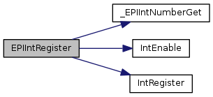
Registers an interrupt handler for the EPI module.

Parameters
ui32Baseis the EPI module base address.
pfnHandleris a pointer to the function to be called when the interrupt is activated.

This sets and enables the handler to be called when the EPI module generates an interrupt. Specific EPI interrupts must still be enabled with the EPIIntEnable() function.

See also
IntRegister() for important information about registering interrupt handlers.
Returns
None.

Definition at line 2111 of file epi.c.

References _EPIIntNumberGet(), ASSERT, EPI0_BASE, IntEnable(), and IntRegister().

2112 {
2113  uint32_t ui32Int;
2114 
2115  //
2116  // Check the arguments.
2117  //
2118  ASSERT(ui32Base == EPI0_BASE);
2119  ASSERT(pfnHandler);
2120 
2121  //
2122  // Get the interrupt number for the EPI interface.
2123  //
2124  ui32Int = _EPIIntNumberGet(ui32Base);
2125 
2126  ASSERT(ui32Int != 0);
2127 
2128  //
2129  // Register the interrupt handler.
2130  //
2131  IntRegister(ui32Int, pfnHandler);
2132 
2133  //
2134  // Enable the EPI interface interrupt.
2135  //
2136  IntEnable(ui32Int);
2137 }
#define ASSERT(expr)
Definition: debug.h:67
#define EPI0_BASE
Definition: hw_memmap.h:129
void IntRegister(uint32_t ui32Interrupt, void(*pfnHandler)(void))
Definition: interrupt.c:309
void IntEnable(uint32_t ui32Interrupt)
Definition: interrupt.c:610
static uint32_t _EPIIntNumberGet(uint32_t ui32Base)
Definition: epi.c:2070

Here is the call graph for this function:

uint32_t EPIIntStatus ( uint32_t  ui32Base,
bool  bMasked 
)

Gets the EPI interrupt status.

Parameters
ui32Baseis the EPI module base address.
bMaskedis set true to get the masked interrupt status, or false to get the raw interrupt status.

This function returns the EPI interrupt status. It can return either the raw or masked interrupt status.

Returns
Returns the masked or raw EPI interrupt status, as a bit field of any of the following values:
  • EPI_INT_TXREQ interrupt when transmit FIFO is below the trigger level.
  • EPI_INT_RXREQ interrupt when read FIFO is above the trigger level.
  • EPI_INT_ERR interrupt when an error condition occurs.
  • EPI_INT_DMA_TX_DONE interrupt when the transmit DMA completes.
  • EPI_INT_DMA_RX_DONE interrupt when the read DMA completes.

Definition at line 1963 of file epi.c.

References ASSERT, EPI0_BASE, EPI_O_MIS, EPI_O_RIS, and HWREG.

1964 {
1965  //
1966  // Check the arguments.
1967  //
1968  ASSERT(ui32Base == EPI0_BASE);
1969 
1970  //
1971  // Return either the interrupt status or the raw interrupt status as
1972  // requested.
1973  //
1974  if(bMasked)
1975  {
1976  return(HWREG(ui32Base + EPI_O_MIS));
1977  }
1978  else
1979  {
1980  return(HWREG(ui32Base + EPI_O_RIS));
1981  }
1982 }
#define HWREG(x)
Definition: hw_types.h:48
#define EPI_O_MIS
Definition: hw_epi.h:81
#define ASSERT(expr)
Definition: debug.h:67
#define EPI_O_RIS
Definition: hw_epi.h:80
#define EPI0_BASE
Definition: hw_memmap.h:129
void EPIIntUnregister ( uint32_t  ui32Base)

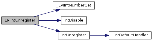
Removes a registered interrupt handler for the EPI module.

Parameters
ui32Baseis the EPI module base address.

This function disables and clears the handler to be called when the EPI interrupt occurs.

See also
IntRegister() for important information about registering interrupt handlers.
Returns
None.

Definition at line 2155 of file epi.c.

References _EPIIntNumberGet(), ASSERT, EPI0_BASE, IntDisable(), and IntUnregister().

2156 {
2157  uint32_t ui32Int;
2158 
2159  //
2160  // Check the arguments.
2161  //
2162  ASSERT(ui32Base == EPI0_BASE);
2163 
2164  //
2165  // Get the interrupt number for the EPI interface.
2166  //
2167  ui32Int = _EPIIntNumberGet(ui32Base);
2168 
2169  ASSERT(ui32Int != 0);
2170 
2171  //
2172  // Disable the EPI interface interrupt.
2173  //
2174  IntDisable(ui32Int);
2175 
2176  //
2177  // Unregister the interrupt handler.
2178  //
2179  IntUnregister(ui32Int);
2180 }
#define ASSERT(expr)
Definition: debug.h:67
#define EPI0_BASE
Definition: hw_memmap.h:129
void IntUnregister(uint32_t ui32Interrupt)
Definition: interrupt.c:381
void IntDisable(uint32_t ui32Interrupt)
Definition: interrupt.c:684
static uint32_t _EPIIntNumberGet(uint32_t ui32Base)
Definition: epi.c:2070

Here is the call graph for this function:

void EPIModeSet ( uint32_t  ui32Base,
uint32_t  ui32Mode 
)

Sets the usage mode of the EPI module.

Parameters
ui32Baseis the EPI module base address.
ui32Modeis the usage mode of the EPI module.

This functions sets the operating mode of the EPI module. The parameter ui32Mode must be one of the following:

  • EPI_MODE_GENERAL - use for general-purpose mode operation
  • EPI_MODE_SDRAM - use with SDRAM device
  • EPI_MODE_HB8 - use with host-bus 8-bit interface
  • EPI_MODE_HB16 - use with host-bus 16-bit interface
  • EPI_MODE_DISABLE - disable the EPI module

Selection of any of the above modes enables the EPI module, except for EPI_MODE_DISABLE, which is used to disable the module.

Returns
None.

Definition at line 252 of file epi.c.

References ASSERT, EPI0_BASE, EPI_MODE_DISABLE, EPI_MODE_GENERAL, EPI_MODE_HB16, EPI_MODE_HB8, EPI_MODE_SDRAM, EPI_O_CFG, and HWREG.

253 {
254  //
255  // Check the arguments.
256  //
257  ASSERT(ui32Base == EPI0_BASE);
258  ASSERT((ui32Mode == EPI_MODE_GENERAL) ||
259  (ui32Mode == EPI_MODE_SDRAM) ||
260  (ui32Mode == EPI_MODE_HB8) ||
261  (ui32Mode == EPI_MODE_HB16) ||
262  (ui32Mode == EPI_MODE_DISABLE));
263 
264  //
265  // Write the mode word to the register.
266  //
267  HWREG(ui32Base + EPI_O_CFG) = ui32Mode;
268 }
#define HWREG(x)
Definition: hw_types.h:48
#define ASSERT(expr)
Definition: debug.h:67
#define EPI_MODE_HB16
Definition: epi.h:62
#define EPI_MODE_GENERAL
Definition: epi.h:59
#define EPI0_BASE
Definition: hw_memmap.h:129
#define EPI_MODE_DISABLE
Definition: epi.h:63
#define EPI_MODE_HB8
Definition: epi.h:61
#define EPI_O_CFG
Definition: hw_epi.h:49
#define EPI_MODE_SDRAM
Definition: epi.h:60
uint32_t EPINonBlockingReadAvail ( uint32_t  ui32Base)

Get the count of items available in the read FIFO.

Parameters
ui32Baseis the EPI module base address.

This function gets the number of items that are available to read in the read FIFO. The read FIFO is filled by a non-blocking read transaction which is configured by the functions EPINonBlockingReadConfigure() and EPINonBlockingReadStart().

Returns
The number of items available to read in the read FIFO.

Definition at line 1620 of file epi.c.

References ASSERT, EPI0_BASE, EPI_O_RFIFOCNT, and HWREG.

1621 {
1622  //
1623  // Check the arguments.
1624  //
1625  ASSERT(ui32Base == EPI0_BASE);
1626 
1627  //
1628  // Read the FIFO count and return it to the caller.
1629  //
1630  return(HWREG(ui32Base + EPI_O_RFIFOCNT));
1631 }
#define HWREG(x)
Definition: hw_types.h:48
#define ASSERT(expr)
Definition: debug.h:67
#define EPI0_BASE
Definition: hw_memmap.h:129
#define EPI_O_RFIFOCNT
Definition: hw_epi.h:67
void EPINonBlockingReadConfigure ( uint32_t  ui32Base,
uint32_t  ui32Channel,
uint32_t  ui32DataSize,
uint32_t  ui32Address 
)

Configures a non-blocking read transaction.

Parameters
ui32Baseis the EPI module base address.
ui32Channelis the read channel (0 or 1).
ui32DataSizeis the size of the data items to read.
ui32Addressis the starting address to read.

This function is used to configure a non-blocking read channel for a transaction. Two channels are available that can be used in a ping-pong method for continuous reading. It is not necessary to use both channels to perform a non-blocking read.

The parameter ui8DataSize is one of EPI_NBCONFIG_SIZE_8, EPI_NBCONFIG_SIZE_16, or EPI_NBCONFIG_SIZE_32 for 8-bit, 16-bit, or 32-bit sized data transfers.

The parameter ui32Address is the starting address for the read, relative to the external device. The start of the device is address 0.

Once configured, the non-blocking read is started by calling EPINonBlockingReadStart(). If the addresses to be read from the device are in a sequence, it is not necessary to call this function multiple times. Until it is changed, the EPI module stores the last address that was used for a non-blocking read (per channel).

Returns
None.

Definition at line 1460 of file epi.c.

References ASSERT, EPI0_BASE, EPI_O_RADDR0, EPI_O_RSIZE0, EPI_O_RSIZE1, and HWREG.

1462 {
1463  uint32_t ui32Offset;
1464 
1465  //
1466  // Check the arguments.
1467  //
1468  ASSERT(ui32Base == EPI0_BASE);
1469  ASSERT(ui32Channel < 2);
1470  ASSERT(ui32DataSize < 4);
1471  ASSERT(ui32Address < 0x20000000);
1472 
1473  //
1474  // Compute the offset needed to select the correct channel regs.
1475  //
1476  ui32Offset = ui32Channel * (EPI_O_RSIZE1 - EPI_O_RSIZE0);
1477 
1478  //
1479  // Write the data size register for the channel.
1480  //
1481  HWREG(ui32Base + EPI_O_RSIZE0 + ui32Offset) = ui32DataSize;
1482 
1483  //
1484  // Write the starting address register for the channel.
1485  //
1486  HWREG(ui32Base + EPI_O_RADDR0 + ui32Offset) = ui32Address;
1487 }
#define HWREG(x)
Definition: hw_types.h:48
#define EPI_O_RSIZE0
Definition: hw_epi.h:60
#define ASSERT(expr)
Definition: debug.h:67
#define EPI_O_RSIZE1
Definition: hw_epi.h:63
#define EPI0_BASE
Definition: hw_memmap.h:129
#define EPI_O_RADDR0
Definition: hw_epi.h:61
uint32_t EPINonBlockingReadCount ( uint32_t  ui32Base,
uint32_t  ui32Channel 
)

Get the count remaining for a non-blocking transaction.

Parameters
ui32Baseis the EPI module base address.
ui32Channelis the read channel (0 or 1).

This function gets the remaining count of items for a non-blocking read transaction.

Returns
The number of items remaining in the non-blocking read transaction.

Definition at line 1584 of file epi.c.

References ASSERT, EPI0_BASE, EPI_O_RPSTD0, EPI_O_RPSTD1, and HWREG.

1585 {
1586  uint32_t ui32Offset;
1587 
1588  //
1589  // Check the arguments.
1590  //
1591  ASSERT(ui32Base == EPI0_BASE);
1592  ASSERT(ui32Channel < 2);
1593 
1594  //
1595  // Compute the offset needed to select the correct channel regs.
1596  //
1597  ui32Offset = ui32Channel * (EPI_O_RPSTD1 - EPI_O_RPSTD0);
1598 
1599  //
1600  // Read the count remaining and return the value to the caller.
1601  //
1602  return(HWREG(ui32Base + EPI_O_RPSTD0 + ui32Offset));
1603 }
#define HWREG(x)
Definition: hw_types.h:48
#define EPI_O_RPSTD0
Definition: hw_epi.h:62
#define ASSERT(expr)
Definition: debug.h:67
#define EPI0_BASE
Definition: hw_memmap.h:129
#define EPI_O_RPSTD1
Definition: hw_epi.h:65
uint32_t EPINonBlockingReadGet16 ( uint32_t  ui32Base,
uint32_t  ui32Count,
uint16_t *  pui16Buf 
)

Read available data from the read FIFO, as 16-bit data items.

Parameters
ui32Baseis the EPI module base address.
ui32Countis the maximum count of items to read.
pui16Bufis the caller-supplied buffer where the read data is stored.

This function reads 16-bit data items from the read FIFO and stores the values in a caller-supplied buffer. The function reads and stores data from the FIFO until there is no more data in the FIFO or the maximum count is reached as specified in the parameter ui32Count. The actual count of items is returned.

Returns
The number of items read from the FIFO.

Definition at line 1707 of file epi.c.

References ASSERT, EPI0_BASE, EPI_O_READFIFO0, EPI_O_RFIFOCNT, and HWREG.

1709 {
1710  uint32_t ui32CountRead = 0;
1711 
1712  //
1713  // Check the arguments.
1714  //
1715  ASSERT(ui32Base == EPI0_BASE);
1716  ASSERT(ui32Count < 4096);
1717  ASSERT(pui16Buf);
1718 
1719  //
1720  // Read from the FIFO while there are any items to read, and
1721  // the caller's specified count is not exceeded.
1722  //
1723  while(HWREG(ui32Base + EPI_O_RFIFOCNT) && ui32Count--)
1724  {
1725  //
1726  // Read from the FIFO and store in the caller-supplied buffer.
1727  //
1728  *pui16Buf = (uint16_t)HWREG(ui32Base + EPI_O_READFIFO0);
1729 
1730  //
1731  // Update the caller's buffer pointer and the count of items read.
1732  //
1733  pui16Buf++;
1734  ui32CountRead++;
1735  }
1736 
1737  //
1738  // Return the count of items read to the caller.
1739  //
1740  return(ui32CountRead);
1741 }
#define HWREG(x)
Definition: hw_types.h:48
#define ASSERT(expr)
Definition: debug.h:67
#define EPI0_BASE
Definition: hw_memmap.h:129
#define EPI_O_READFIFO0
Definition: hw_epi.h:68
#define EPI_O_RFIFOCNT
Definition: hw_epi.h:67
uint32_t EPINonBlockingReadGet32 ( uint32_t  ui32Base,
uint32_t  ui32Count,
uint32_t *  pui32Buf 
)

Read available data from the read FIFO, as 32-bit data items.

Parameters
ui32Baseis the EPI module base address.
ui32Countis the maximum count of items to read.
pui32Bufis the caller supplied buffer where the read data is stored.

This function reads 32-bit data items from the read FIFO and stores the values in a caller-supplied buffer. The function reads and stores data from the FIFO until there is no more data in the FIFO or the maximum count is reached as specified in the parameter ui32Count. The actual count of items is returned.

Returns
The number of items read from the FIFO.

Definition at line 1652 of file epi.c.

References ASSERT, EPI0_BASE, EPI_O_READFIFO0, EPI_O_RFIFOCNT, and HWREG.

1654 {
1655  uint32_t ui32CountRead = 0;
1656 
1657  //
1658  // Check the arguments.
1659  //
1660  ASSERT(ui32Base == EPI0_BASE);
1661  ASSERT(ui32Count < 4096);
1662  ASSERT(pui32Buf);
1663 
1664  //
1665  // Read from the FIFO while there are any items to read and
1666  // the caller's specified count is not exceeded.
1667  //
1668  while(HWREG(ui32Base + EPI_O_RFIFOCNT) && ui32Count--)
1669  {
1670  //
1671  // Read from the FIFO and store in the caller supplied buffer.
1672  //
1673  *pui32Buf = HWREG(ui32Base + EPI_O_READFIFO0);
1674 
1675  //
1676  // Update the caller's buffer pointer and the count of items read.
1677  //
1678  pui32Buf++;
1679  ui32CountRead++;
1680  }
1681 
1682  //
1683  // Return the count of items read to the caller.
1684  //
1685  return(ui32CountRead);
1686 }
#define HWREG(x)
Definition: hw_types.h:48
#define ASSERT(expr)
Definition: debug.h:67
#define EPI0_BASE
Definition: hw_memmap.h:129
#define EPI_O_READFIFO0
Definition: hw_epi.h:68
#define EPI_O_RFIFOCNT
Definition: hw_epi.h:67
uint32_t EPINonBlockingReadGet8 ( uint32_t  ui32Base,
uint32_t  ui32Count,
uint8_t *  pui8Buf 
)

Read available data from the read FIFO, as 8-bit data items.

Parameters
ui32Baseis the EPI module base address.
ui32Countis the maximum count of items to read.
pui8Bufis the caller-supplied buffer where the read data is stored.

This function reads 8-bit data items from the read FIFO and stores the values in a caller-supplied buffer. The function reads and stores data from the FIFO until there is no more data in the FIFO or the maximum count is reached as specified in the parameter ui32Count. The actual count of items is returned.

Returns
The number of items read from the FIFO.

Definition at line 1762 of file epi.c.

References ASSERT, EPI0_BASE, EPI_O_READFIFO0, EPI_O_RFIFOCNT, and HWREG.

1764 {
1765  uint32_t ui32CountRead = 0;
1766 
1767  //
1768  // Check the arguments.
1769  //
1770  ASSERT(ui32Base == EPI0_BASE);
1771  ASSERT(ui32Count < 4096);
1772  ASSERT(pui8Buf);
1773 
1774  //
1775  // Read from the FIFO while there are any items to read, and
1776  // the caller's specified count is not exceeded.
1777  //
1778  while(HWREG(ui32Base + EPI_O_RFIFOCNT) && ui32Count--)
1779  {
1780  //
1781  // Read from the FIFO and store in the caller supplied buffer.
1782  //
1783  *pui8Buf = (uint8_t)HWREG(ui32Base + EPI_O_READFIFO0);
1784 
1785  //
1786  // Update the caller's buffer pointer and the count of items read.
1787  //
1788  pui8Buf++;
1789  ui32CountRead++;
1790  }
1791 
1792  //
1793  // Return the count of items read to the caller.
1794  //
1795  return(ui32CountRead);
1796 }
#define HWREG(x)
Definition: hw_types.h:48
#define ASSERT(expr)
Definition: debug.h:67
#define EPI0_BASE
Definition: hw_memmap.h:129
#define EPI_O_READFIFO0
Definition: hw_epi.h:68
#define EPI_O_RFIFOCNT
Definition: hw_epi.h:67
void EPINonBlockingReadStart ( uint32_t  ui32Base,
uint32_t  ui32Channel,
uint32_t  ui32Count 
)

Starts a non-blocking read transaction.

Parameters
ui32Baseis the EPI module base address.
ui32Channelis the read channel (0 or 1).
ui32Countis the number of items to read (1-4095).

This function starts a non-blocking read that was previously configured with the function EPINonBlockingReadConfigure(). Once this function is called, the EPI module begins reading data from the external device into the read FIFO. The EPI stops reading when the FIFO fills up and resumes reading when the application drains the FIFO, until the total specified count of data items has been read.

Once a read transaction is completed and the FIFO drained, another transaction can be started from the next address by calling this function again.

Returns
None.

Definition at line 1512 of file epi.c.

References ASSERT, EPI0_BASE, EPI_O_RPSTD0, EPI_O_RPSTD1, and HWREG.

1514 {
1515  uint32_t ui32Offset;
1516 
1517  //
1518  // Check the arguments.
1519  //
1520  ASSERT(ui32Base == EPI0_BASE);
1521  ASSERT(ui32Channel < 2);
1522  ASSERT(ui32Count < 4096);
1523 
1524  //
1525  // Compute the offset needed to select the correct channel regs.
1526  //
1527  ui32Offset = ui32Channel * (EPI_O_RPSTD1 - EPI_O_RPSTD0);
1528 
1529  //
1530  // Write to the read count register.
1531  //
1532  HWREG(ui32Base + EPI_O_RPSTD0 + ui32Offset) = ui32Count;
1533 }
#define HWREG(x)
Definition: hw_types.h:48
#define EPI_O_RPSTD0
Definition: hw_epi.h:62
#define ASSERT(expr)
Definition: debug.h:67
#define EPI0_BASE
Definition: hw_memmap.h:129
#define EPI_O_RPSTD1
Definition: hw_epi.h:65
void EPINonBlockingReadStop ( uint32_t  ui32Base,
uint32_t  ui32Channel 
)

Stops a non-blocking read transaction.

Parameters
ui32Baseis the EPI module base address.
ui32Channelis the read channel (0 or 1).

This function cancels a non-blocking read transaction that is already in progress.

Returns
None.

Definition at line 1549 of file epi.c.

References ASSERT, EPI0_BASE, EPI_O_RPSTD0, EPI_O_RPSTD1, and HWREG.

1550 {
1551  uint32_t ui32Offset;
1552 
1553  //
1554  // Check the arguments.
1555  //
1556  ASSERT(ui32Base == EPI0_BASE);
1557  ASSERT(ui32Channel < 2);
1558 
1559  //
1560  // Compute the offset needed to select the correct channel regs.
1561  //
1562  ui32Offset = ui32Channel * (EPI_O_RPSTD1 - EPI_O_RPSTD0);
1563 
1564  //
1565  // Write a 0 to the read count register, which cancels the transaction.
1566  //
1567  HWREG(ui32Base + EPI_O_RPSTD0 + ui32Offset) = 0;
1568 }
#define HWREG(x)
Definition: hw_types.h:48
#define EPI_O_RPSTD0
Definition: hw_epi.h:62
#define ASSERT(expr)
Definition: debug.h:67
#define EPI0_BASE
Definition: hw_memmap.h:129
#define EPI_O_RPSTD1
Definition: hw_epi.h:65
uint32_t EPIPSRAMConfigRegGet ( uint32_t  ui32Base,
uint32_t  ui32CS 
)

Retrieves the contents of the EPI PSRAM configuration register.

Parameters
ui32Baseis the EPI module base address.
ui32CSis the chip select target.

This function retrieves the EPI PSRAM configuration register. The register is read once the EPI PSRAM configuration register read enable signal is de-asserted.

The Host-bus 16 interface mode should be set up and EPIPSRAMConfigRegRead() should be called prior to calling this function.

The ui32Base parameter is the base address for the EPI hardware module. The ui32CS parameter specifies the chip select to configure and has a valid range of 0-3.

Note
The availability of PSRAM support varies based on the Tiva part in use. Please consult the data sheet to determine if this feature is available.
Returns
none.

Definition at line 1258 of file epi.c.

References ASSERT, EPI0_BASE, EPI_HB16CFG_RDCRE, EPI_O_HB16CFG, EPI_O_HB16CFG3, EPI_O_HBPSRAM, and HWREG.

1259 {
1260  uint32_t ui32Offset;
1261 
1262  //
1263  // Check the arguments.
1264  //
1265  ASSERT(ui32Base == EPI0_BASE);
1266  ASSERT(ui32CS < 4);
1267 
1268  //
1269  // Determine the register offset based on the ui32CS provided.
1270  //
1271  if(ui32CS < 2)
1272  {
1273  ui32Offset = EPI_O_HB16CFG + (ui32CS << 2);
1274  }
1275  else
1276  {
1277  ui32Offset = EPI_O_HB16CFG3 + ((ui32CS - 2) << 2);
1278  }
1279 
1280  //
1281  // Wait for PSRAM read enable to deassert if necessary.
1282  //
1283  while(HWREG(ui32Base + ui32Offset) & EPI_HB16CFG_RDCRE)
1284  {
1285  }
1286 
1287  //
1288  // Return the EPI PSRAM configuration register contents.
1289  // Only the lower 16 bits are valid on a read.
1290  //
1291  return(HWREG(ui32Base + EPI_O_HBPSRAM) & 0xffff);
1292 }
#define HWREG(x)
Definition: hw_types.h:48
#define ASSERT(expr)
Definition: debug.h:67
#define EPI_HB16CFG_RDCRE
Definition: hw_epi.h:148
#define EPI_O_HB16CFG3
Definition: hw_epi.h:85
#define EPI_O_HB16CFG
Definition: hw_epi.h:52
#define EPI0_BASE
Definition: hw_memmap.h:129
#define EPI_O_HBPSRAM
Definition: hw_epi.h:96
bool EPIPSRAMConfigRegGetNonBlocking ( uint32_t  ui32Base,
uint32_t  ui32CS,
uint32_t *  pui32CR 
)

Retrieves the contents of the EPI PSRAM configuration register.

Parameters
ui32Baseis the EPI module base address.
ui32CSis the chip select target.
pui32CRis the provided storage used to hold the register value.

This function copies the contents of the EPI PSRAM configuration register to the provided storage if the PSRAM read configuration register enable is no longer asserted. Otherwise the provided storage is not modified.

The Host-bus 16 interface mode should be set up and EPIPSRAMConfigRegRead() should be called prior to calling this function.

The ui32Base parameter is the base address for the EPI hardware module. The ui32CS parameter specifies the chip select to configure and has a valid range of 0-3. The pui32CR parameter is a pointer to provided storage used to hold the register value.

Note
The availability of PSRAM support varies based on the Tiva part in use. Please consult the data sheet to determine if this feature is available.
Returns
true if the value was copied to the provided storage and false if it was not.

Definition at line 1188 of file epi.c.

References ASSERT, EPI0_BASE, EPI_HB16CFG_RDCRE, EPI_O_HB16CFG, EPI_O_HB16CFG3, EPI_O_HBPSRAM, and HWREG.

1190 {
1191  uint32_t ui32Offset;
1192 
1193  //
1194  // Check the arguments.
1195  //
1196  ASSERT(ui32Base == EPI0_BASE);
1197  ASSERT(ui32CS < 4);
1198 
1199  //
1200  // Determine the register offset based on the ui32CS provided.
1201  //
1202  if(ui32CS < 2)
1203  {
1204  ui32Offset = EPI_O_HB16CFG + (ui32CS << 2);
1205  }
1206  else
1207  {
1208  ui32Offset = EPI_O_HB16CFG3 + ((ui32CS - 2) << 2);
1209  }
1210 
1211  //
1212  // Verify PSRAM read enable is not asserted.
1213  //
1214  if(HWREG(ui32Base + ui32Offset) & EPI_HB16CFG_RDCRE)
1215  {
1216  return(false);
1217  }
1218 
1219  //
1220  // Copy the PSRAM configuration register value to the provided storage.
1221  // Only the lower 16 bits are valid on a read.
1222  //
1223  *pui32CR = HWREG(ui32Base + EPI_O_HBPSRAM) & 0xffff;
1224 
1225  //
1226  // Notify caller the provided storage holds the EPI PSRAM configuration
1227  // register contents.
1228  //
1229  return(true);
1230 }
#define HWREG(x)
Definition: hw_types.h:48
#define ASSERT(expr)
Definition: debug.h:67
#define EPI_HB16CFG_RDCRE
Definition: hw_epi.h:148
#define EPI_O_HB16CFG3
Definition: hw_epi.h:85
#define EPI_O_HB16CFG
Definition: hw_epi.h:52
#define EPI0_BASE
Definition: hw_memmap.h:129
#define EPI_O_HBPSRAM
Definition: hw_epi.h:96
void EPIPSRAMConfigRegRead ( uint32_t  ui32Base,
uint32_t  ui32CS 
)

Requests a configuration register read from the PSRAM.

Parameters
ui32Baseis the EPI module base address.
ui32CSis the chip select target.

This function requests a read of the PSRAM's configuration register. The Host-bus 16 interface mode should be configured prior to calling this function. The EPIPSRAMConfigRegGet() and EPIPSRAMConfigRegGetNonBlocking() can be used to retrieve the configuration register value.

The ui32Base parameter is the base address for the EPI hardware module. The ui32CS parameter specifies the chip select to configure and has a valid range of 0-3.

Note
The availability of PSRAM support varies based on the Tiva part in use. Please consult the data sheet to determine if this feature is available.
Returns
none.

Definition at line 1131 of file epi.c.

References ASSERT, EPI0_BASE, EPI_HB16CFG_RDCRE, EPI_O_HB16CFG, EPI_O_HB16CFG3, and HWREG.

1132 {
1133  uint32_t ui32Offset;
1134 
1135  //
1136  // Check the arguments.
1137  //
1138  ASSERT(ui32Base == EPI0_BASE);
1139  ASSERT(ui32CS < 4);
1140 
1141  //
1142  // Determine the register offset based on the ui32CS provided.
1143  //
1144  if(ui32CS < 2)
1145  {
1146  ui32Offset = EPI_O_HB16CFG + (ui32CS << 2);
1147  }
1148  else
1149  {
1150  ui32Offset = EPI_O_HB16CFG3 + ((ui32CS - 2) << 2);
1151  }
1152 
1153  //
1154  // Set the PSRAM configuration register read enable.
1155  //
1156  HWREG(ui32Base + ui32Offset) |= EPI_HB16CFG_RDCRE;
1157 }
#define HWREG(x)
Definition: hw_types.h:48
#define ASSERT(expr)
Definition: debug.h:67
#define EPI_HB16CFG_RDCRE
Definition: hw_epi.h:148
#define EPI_O_HB16CFG3
Definition: hw_epi.h:85
#define EPI_O_HB16CFG
Definition: hw_epi.h:52
#define EPI0_BASE
Definition: hw_memmap.h:129
void EPIPSRAMConfigRegSet ( uint32_t  ui32Base,
uint32_t  ui32CS,
uint32_t  ui32CR 
)

Sets the PSRAM configuration register.

Parameters
ui32Baseis the EPI module base address.
ui32CSis the chip select target.
ui32CRis the PSRAM configuration register value.

This function sets the PSRAM's configuration register by using the PSRAM configuration register enable signal. The Host-bus 16 interface mode should be configured prior to calling this function.

The ui32Base parameter is the base address for the EPI hardware module. The ui32CS parameter specifies the chip select to configure and has a valid range of 0-3. The parameter ui32CR value is determined by consulting the PSRAM's data sheet.

Note
The availability of PSRAM support varies based on the Tiva part in use. Please consult the data sheet to determine if this feature is available.
Returns
None.

Definition at line 1072 of file epi.c.

References ASSERT, EPI0_BASE, EPI_HB16CFG_WRCRE, EPI_O_HB16CFG, EPI_O_HB16CFG3, EPI_O_HBPSRAM, and HWREG.

1073 {
1074  uint32_t ui32Offset;
1075 
1076  //
1077  // Check the arguments.
1078  //
1079  ASSERT(ui32Base == EPI0_BASE);
1080  ASSERT(ui32CS < 4);
1081 
1082  //
1083  // Determine the register offset based on the ui32CS provided.
1084  //
1085  if(ui32CS < 2)
1086  {
1087  ui32Offset = EPI_O_HB16CFG + (ui32CS << 2);
1088  }
1089  else
1090  {
1091  ui32Offset = EPI_O_HB16CFG3 + ((ui32CS - 2) << 2);
1092  }
1093 
1094  //
1095  // Setup for the PSRAM configuration register write. Only 21 bits are
1096  // valid on a write.
1097  //
1098  HWREG(ui32Base + EPI_O_HBPSRAM) = (ui32CR & 0x1fffff);
1099 
1100  //
1101  // Set the PSRAM configuration register write enable.
1102  //
1103  HWREG(ui32Base + ui32Offset) |= EPI_HB16CFG_WRCRE;
1104 }
#define HWREG(x)
Definition: hw_types.h:48
#define ASSERT(expr)
Definition: debug.h:67
#define EPI_O_HB16CFG3
Definition: hw_epi.h:85
#define EPI_O_HB16CFG
Definition: hw_epi.h:52
#define EPI0_BASE
Definition: hw_memmap.h:129
#define EPI_HB16CFG_WRCRE
Definition: hw_epi.h:146
#define EPI_O_HBPSRAM
Definition: hw_epi.h:96
uint8_t EPIWorkaroundByteRead ( uint8_t *  pui8Addr)

Safely reads a byte from the EPI 0x10000000 address space.

Parameters
pui8Addris the address which is to be read.

This function must be used when reading bytes from EPI-attached memory configured to use the address space at 0x10000000 on devices affected by the EPI#01 erratum. Direct access to memory in these cases can cause data corruption depending upon memory accesses immediately before or after the EPI access but using this function will allow EPI accesses to complete correctly. The function is defined as ``inline'' in epi.h.

Use of this function on a device not affected by the erratum is safe but will impact performance due to an additional overhead of at least 2 cycles per access. This erratum affects only the 0x10000000 address space typically used to store the LCD controller frame buffer. The 0x60000000 address space is not affected and applications using this address mapping need not use this function.

Returns
The 8-bit byte stored at address pui8Addr.
void EPIWorkaroundByteWrite ( uint8_t *  pui8Addr,
uint8_t  ui8Value 
)

Safely writes a byte to the EPI 0x10000000 address space.

Parameters
pui8Addris the address which is to be written.
ui8Valueis the 8-bit byte to write.

This function must be used when writing bytes to EPI-attached memory configured to use the address space at 0x10000000 on devices affected by the EPI#01 erratum. Direct access to memory in these cases can cause data corruption depending upon memory accesses immediately before or after the EPI access but using this function will allow EPI accesses to complete correctly. The function is defined as ``inline'' in epi.h.

Use of this function on a device not affected by the erratum is safe but will impact performance due to an additional overhead of at least 2 cycles per access. This erratum affects only the 0x10000000 address space typically used to store the LCD controller frame buffer. The 0x60000000 address space is not affected and applications using this address mapping need not use this function.

Returns
None.
uint16_t EPIWorkaroundHWordRead ( uint16_t *  pui16Addr)

Safely reads a half-word from the EPI 0x10000000 address space.

Parameters
pui16Addris the address which is to be read.

This function must be used when reading half-words from EPI-attached memory configured to use the address space at 0x10000000 on devices affected by the EPI#01 erratum. Direct access to memory in these cases can cause data corruption depending upon memory accesses immediately before or after the EPI access but using this function will allow EPI accesses to complete correctly. The function is defined as ``inline'' in epi.h.

Use of this function on a device not affected by the erratum is safe but will impact performance due to an additional overhead of at least 2 cycles per access. This erratum affects only the 0x10000000 address space typically used to store the LCD controller frame buffer. The 0x60000000 address space is not affected and applications using this address mapping need not use this function.

Returns
The 16-bit word stored at address pui16Addr.
void EPIWorkaroundHWordWrite ( uint16_t *  pui16Addr,
uint16_t  ui16Value 
)

Safely writes a half-word to the EPI 0x10000000 address space.

Parameters
pui16Addris the address which is to be written.
ui16Valueis the 16-bit half-word to write.

This function must be used when writing half-words to EPI-attached memory configured to use the address space at 0x10000000 on devices affected by the EPI#01 erratum. Direct access to memory in these cases can cause data corruption depending upon memory accesses immediately before or after the EPI access but using this function will allow EPI accesses to complete correctly. The function is defined as ``inline'' in epi.h.

Use of this function on a device not affected by the erratum is safe but will impact performance due to an additional overhead of at least 2 cycles per access. This erratum affects only the 0x10000000 address space typically used to store the LCD controller frame buffer. The 0x60000000 address space is not affected and applications using this address mapping need not use this function.

Returns
None.
uint32_t EPIWorkaroundWordRead ( uint32_t *  pui32Addr)

Safely reads a word from the EPI 0x10000000 address space.

Parameters
pui32Addris the address which is to be read.

This function must be used when reading words from EPI-attached memory configured to use the address space at 0x10000000 on devices affected by the EPI#01 erratum. Direct access to memory in these cases can cause data corruption depending upon memory accesses immediately before or after the EPI access but using this function will allow EPI accesses to complete correctly. The function is defined as ``inline'' in epi.h.

Use of this function on a device not affected by the erratum is safe but will impact performance due to an additional overhead of at least 2 cycles per access. This erratum affects only the 0x10000000 address space typically used to store the LCD controller frame buffer. The 0x60000000 address space is not affected and applications using this address mapping need not use this function.

Returns
The 32-bit word stored at address pui32Addr.
void EPIWorkaroundWordWrite ( uint32_t *  pui32Addr,
uint32_t  ui32Value 
)

Safely writes a word to the EPI 0x10000000 address space.

Parameters
pui32Addris the address which is to be written.
ui32Valueis the 32-bit word to write.

This function must be used when writing words to EPI-attached memory configured to use the address space at 0x10000000 on devices affected by the EPI#01 erratum. Direct access to memory in these cases can cause data corruption depending upon memory accesses immediately before or after the EPI access but using this function will allow EPI accesses to complete correctly. The function is defined as ``inline'' in epi.h.

Use of this function on a device not affected by the erratum is safe but will impact performance due to an additional overhead of at least 2 cycles per access. This erratum affects only the 0x10000000 address space typically used to store the LCD controller frame buffer. The 0x60000000 address space is not affected and applications using this address mapping need not use this function.

Returns
None.
uint32_t EPIWriteFIFOCountGet ( uint32_t  ui32Base)

Reads the number of empty slots in the write transaction FIFO.

Parameters
ui32Baseis the EPI module base address.

This function returns the number of slots available in the transaction FIFO. It can be used in a polling method to avoid attempting a write that would stall.

Returns
The number of empty slots in the transaction FIFO.

Definition at line 1858 of file epi.c.

References ASSERT, EPI0_BASE, EPI_O_WFIFOCNT, and HWREG.

1859 {
1860  //
1861  // Check the arguments.
1862  //
1863  ASSERT(ui32Base == EPI0_BASE);
1864 
1865  //
1866  // Read the FIFO count and return it to the caller.
1867  //
1868  return(HWREG(ui32Base + EPI_O_WFIFOCNT));
1869 }
#define HWREG(x)
Definition: hw_types.h:48
#define ASSERT(expr)
Definition: debug.h:67
#define EPI0_BASE
Definition: hw_memmap.h:129
#define EPI_O_WFIFOCNT
Definition: hw_epi.h:77